"ground channel" questions
Apr 4, 2006 at 1:18 AM Thread Starter Post #1 of 5

vixr

500+ Head-Fier
Joined
Oct 14, 2005
Posts
988
Likes
24
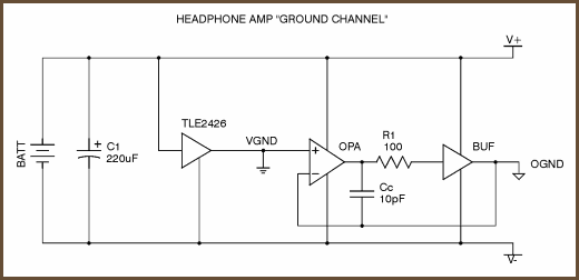
I built Tangents ground channel from his article, node for node, and I have some questions. How is the ground channel tested? I completed 1/2 of the amp and I am getting stooopid high DC offset. Like -6 volts. I put my test leads from the output of the buffer to Ognd and get -6 volts. The ground channel resistor between the OPA132 and the buffer is 100 ohms, with a 100nF cap (all I had) I connected some airline type phones to the right channel and it didn't fry them... I can't tell if it sounds any good, since the phones are crap. When I check buffer output to Vgnd I get like 1.3 mV DC. The amp consists of an OPA2132PA, biased with 2n5484 and 2n5486 and a BUF634, straight from Tangents article on Biasing...I am putting the buffer output back into the op amp thru R3 and R4. R3 is 1K and R4 is 10k. The op amp output is going to ground through the transistors and then to the input of the buffer, exactly like the schematic. Negative 6volts at Ognd??? Oh BTW, it goes VERY loud...
 
Apr 4, 2006 at 1:50 AM Post #2 of 5
Quote:

Originally Posted by vixr
I built Tangents ground channel from his article, node for node, and I have some questions. How is the ground channel tested? I completed 1/2 of the amp and I am getting stooopid high DC offset. Like -6 volts. I put my test leads from the output of the buffer to Ognd and get -6 volts.


Look at this figure here:

gnd-channel.png


OGND and the output from the buffer are the same - nothing is seperating them. Despite what you think, you're not measuring between OGND and the buffer output. I'm guessing you've probably misread the datasheet for the chip and have placed the probe on the wrong pin -- probably the negative power supply pin.

What you want to do is measure from OGND to the ground plane and Virtual Ground, which is the ground plane in this case.

Quote:

When I check buffer output to Vgnd I get like 1.3 mV DC.


That is the DC offset for the ground channel.
 
Apr 4, 2006 at 2:06 AM Post #3 of 5
Ah... I see. Would DC offset in negative be bad? Do I introduce the source ground at Vgnd? I don't see any other point to do so from the schematic. The one you posted is the one I'm using.
 
Apr 4, 2006 at 2:47 AM Post #4 of 5
Negative DC and Positive DC are still both just that. DC imposed on an AC waveform equally nasty, equally likely depending on how things are setup or which part fries.

Yes the only thing connected to Ognd is the headphones. ALl other ground points a connected to the virtual ground.
 
Apr 4, 2006 at 2:51 AM Post #5 of 5
Quote:

Originally Posted by vixr
Ah... I see. Would DC offset in negative be bad? Do I introduce the source ground at Vgnd? I don't see any other point to do so from the schematic. The one you posted is the one I'm using.


Negative DC offset isn't any different than positive offset. You're just measuring a voltage difference relative to virtual ground.

In this case, input ground is connected to virtual ground. I say in this case because I'm not sure if this will always be the case for a three channel set up.
 

Users who are viewing this thread

Back
Top