
MASantos
Headphoneus Supremus
- Joined
- Dec 21, 2004
- Posts
- 2,436
- Likes
- 39
Would the AD8397 OPAMP benifit from class A biasing or would this cause any oscilation/instability problems?
Manuel
Manuel
| Originally Posted by MASantos Would the AD8397 OPAMP benifit from class A biasing |
| would this cause any oscilation/instability problems? |
| Originally Posted by robzy The amount of current you would have to draw might be in the order of hundreds of milliamps |
| Originally Posted by tangent I can't see why. Even with an unrealisticially high load of 2V peak into 32 ohms, you only need 62 mA. That's well within the 8397's abilities. |
| Originally Posted by tangent Why not try it and see? If that's all it takes to destabilize your configuration, you didn't have enough margin to begin with. |
| Originally Posted by tangent Now, problems I do see are: 1. How do you keep the op-amp cool? You'll definitely have to use the EPAD version, and it'll have to be connected to a substantial copper plane. 2. What do you use for the CCS? A lot of the favorites around here won't scale up that high. |
| Originally Posted by robzy Class A biasing is not really possible for opamps driving a headphone load directly. (I assume you dont have a buffer?) http://tangentsoft.net/audio/opamp-bias.html To summarise: The amount of current you would have to draw might be in the order of hundreds of milliamps, which is unrealstic. Rob. |
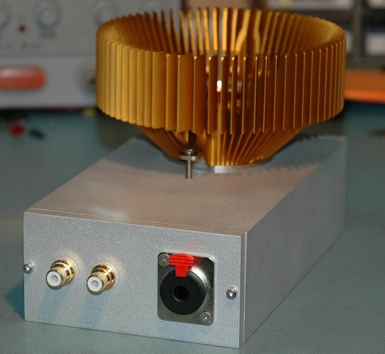
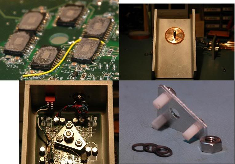
| Originally Posted by jcx Unrealistic but quite doable- isn't that what this hobby is about? http://www6.head-fi.org/forums/showt...pa#post2082883 (scroll up page to see pics) My proto is about Class A output operation over the full range with op amps - yes it does require "order of hundreds of milliamps" - I used ~220mA push-pull (440mA pk) to get 3 Wrms into 32 Ohms - as per Gilmore's recommendation of required headphone power most "class A op amp biasing" you see in headphone op amp circuits is only a few mA for internal stage use it is likely the AD8397 is already working with 3-5 mA pp output stage bias internally to get good MHz distortion specs - so the 1st 5-10mA of output is probably "class A" if you really want to go full ouptut swing Class A you're limited in sucking power out thru the pcb with the EPAD to a few W - heatsink on top of the package won't help much - after all the die/leadframe is deliberately set downward to be exposed on the bottom of the package so you have nearly the full package thickness of molding compound in between - this isn't like a large chip area/thin molding memory or cpu thermal path - the op amp die is small and the plastic molding compound thickness is large which is why I went "belly up" with the heatsink clamped to the exposed thermal pad - I am sucking 6 W from each package from the 2 most heavily loaded chips in my cascaded/paralleled amp - the bigger TPA6120 op amp packages in my amp have the Cu slug Zalman cpu heatsink clamped to the TPA power pads with a few mil smear of Artic Silver in between - pcb power plane heat sinking is for wimps! |

| Originally Posted by robzy is the reason the PIMETA/MINT have buffers after the class-A biased opamps because the opamp did not have the current capability for both the load and the CCS? |
| Originally Posted by MASantos CCS: either a CRD or jfet cascode configured for more current output. |
| Originally Posted by jcx I used ~220mA push-pull (440mA pk) to get 3 Wrms into 32 Ohms - as per Gilmore's recommendation of required headphone power |
| Originally Posted by MASantos Quote:
I don't understand your point. Could you explain this? |
| Originally Posted by tangent As for raw JFETs, when you cascode JFETs, the total current is some fraction of the Idss of the lower JFET, so you want one somewhere up in the 100mA range to hit my 62mA number, and more like 200-300mA to make jcx happy. I did some searching, and couldn't find such a beast. |
| Originally Posted by steinchen just for info: BF246C is such a beast, followed by BF246B and pn4391 |
