_-_Cmoy wiring driving me MAD!_-_
Jun 17, 2003 at 9:37 PM Thread Starter Post #1 of 12

sonichead

100+ Head-Fier
Joined
Mar 1, 2003
Posts
180
Likes
0
I'm having a terrible time testing my Cmoy, I've yet to see any results after doing all kinds of things with aligator clips. (I have a 150 board finished) Nothing works, not even a hum!
mad.gif


Thus far, I know I need to solder the output jack to the two output pins on the board, and also to the ground spot on the board.

As for everything else (input jack, and POT) I am totally baffled! I think the input jack goes through the pot before it gets to the board, but I am not sure.

I am using the 6 pin panasonic pot:
1) L - output
2) Ground
3) Ground
4) R - output
5) R - input
6) L - input (when looking at the pins with the rod pointing at the sky)

And here's the board:
mini-cmoy--150-ann-board-2.jpg


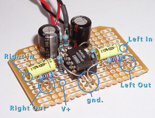
Can anyone explain how to wire the pot and input jack?

Edit: What is the v+ thing in the picture, do I need to connect that to anything or jump it?
 
Jun 17, 2003 at 9:48 PM Post #2 of 12
Didn't we have this a few days ago? Ok, second try.
There are three connections on the input jack. Left (tip), Right (ring) and Ground (sleeve).

The Ground goes to 'gnd' on your board.
Left goes to the left input of the pot. The left output of your pot then goes to 'l.in' on the board. The pot's left ground is connected to board 'gnd'. Same for the right channel: input jack->pot input; pot output->board input; pot ground->board ground

you need to run a wire from the 'v+ thing' to the supply voltage (Edit: and as this is the supply for the opamp, omitting this means nothing will work...)
 
Jun 17, 2003 at 9:51 PM Post #3 of 12
Quote:

Originally posted by PeterR
Didn't we have this a few days ago? Ok, second try... you need to run a wire from the 'v+ thing' to the supply voltage.


Yes, we did!

Ok, where is the "voltage supply" i need to connect the V+ spot to?
 
Jun 17, 2003 at 9:55 PM Post #4 of 12
Quote:

you need to run a wire from the 'v+ thing' to the supply voltage.


..unless you already have the power
hooked up. If you do, the "v+" shouldn't
be connected to anything...

I'm having a strange feeling of d&#233j&#224 vu...
 
Jun 17, 2003 at 9:56 PM Post #5 of 12
Connect a wire to the V+ pad near the power caps.
Do the same for the v- pad.

These wires connect to your battery.
 
Jun 17, 2003 at 9:58 PM Post #6 of 12
this post is now useless
 
Jun 17, 2003 at 10:06 PM Post #8 of 12
Yes, that's what that wire is, I presume; a jumper
from that pad to V+ near the cap.

You need this to power the op amp.
There should also be a jumper, or wire, from the V- pad to the V- pin of the opa.
 
Jun 17, 2003 at 10:09 PM Post #9 of 12
Thanks guys, I was making that picture myself but peter beat me to it!
 
Jun 18, 2003 at 5:06 AM Post #10 of 12
Aren't his C1 caps (in the amp circuit, not the power supply) too small? They don't even connect to the pads where his test wires stick up (and presumably where his inputs will be.)

That's a pretty big spark gap for a line-level signal to jump...

eek.gif
eek.gif
eek.gif


GnD
 

Users who are viewing this thread

Back
Top