To Cyber Theo
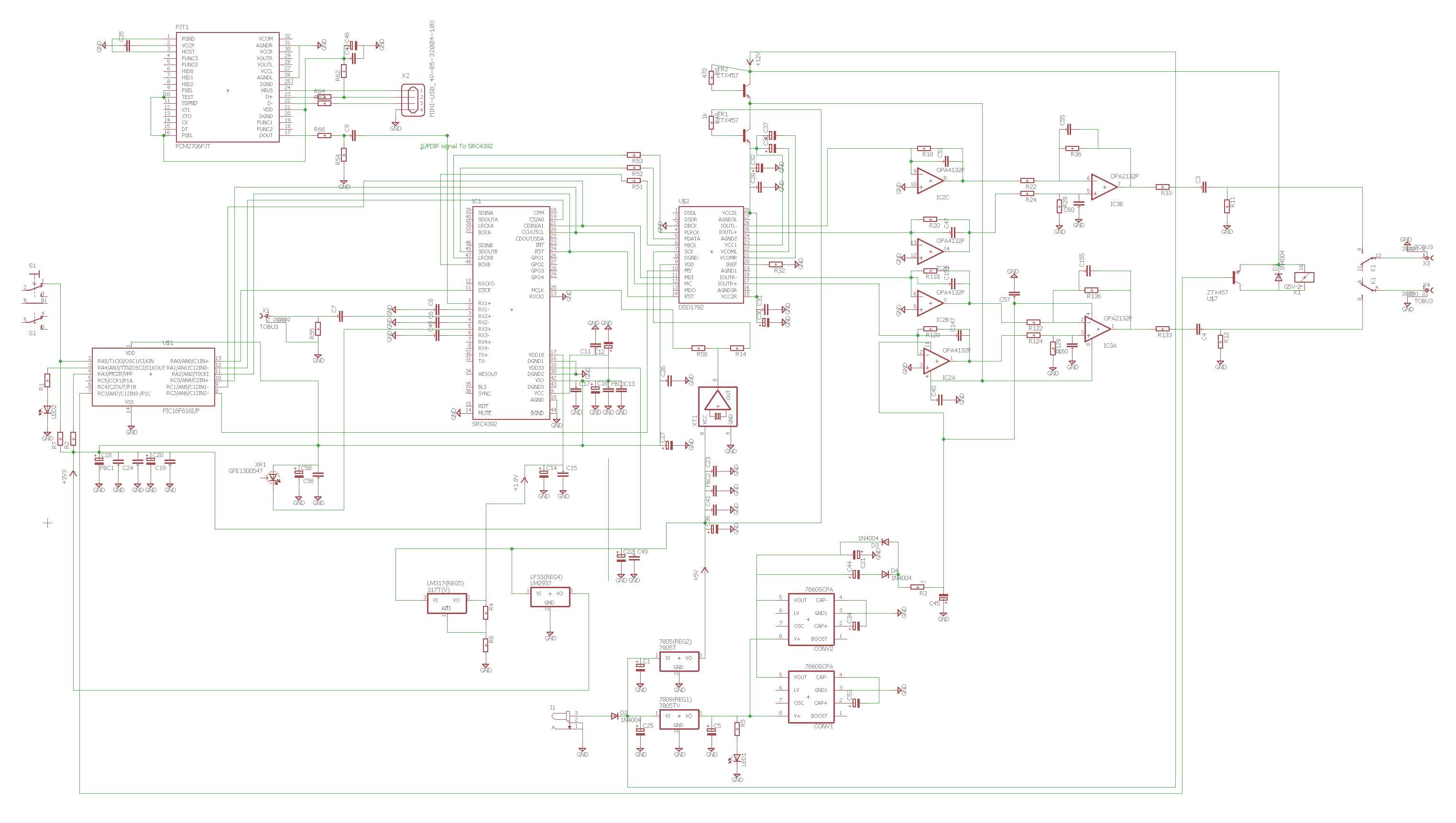
The thread has examples of replacing the two 47uF output caps with 3,3uF or 4,7uF Mkp caps. I happen to have a pair of Cornell-Dubilier 3,3uF Mkp in my parts bin. How safe is it to use 3,3uF in these positions, as they are significantly lower than the stock 47uF value? Would it damage the circuit though prolonged use?
47uF is worse case possible the manufacture doesnt know what is behind the v-dac for resistor (pre-amp), so they take a value (overkill) 47uf
But i have made a little computing and came out on 2,5uF but knowing some users differ so 4,7 is more then enough.
Dont use elco or bip/elco
USE MKP at least, elcos have a much higher distortion then MKP its called the D.A. factor, deelectric absortion
Read
http://en.wikipedia.org/wiki/Dielectric_absorption
Aslong the cap gives values till 0,0002% are good over the 1 is like a elco some do make 10%
In other words, Mkp passes all audio freq. but elco is a one way conductor like a batterij, bip. elco is two ways -+ or+- ,Mkp is allways two ways.
Indeed when the value is too low the bass will disapear you need some capacity to load.
I hope you understand my explanation.
change opamps
Dis solder a opamp is little tricky when expensive ones, if you want to save a 5532 (costs 1-2 € looool)
Cut the pins on headside with side-cutter and dissolder the pins from the tin solder side, easier.
Note when you want to tweak with other opamps, you can place a dil8 foot so you can switch with other opamps later on.
Most important dont overheat the pcb board then you will loose some copper from the pcb board