


wrathzombie
Headphoneus Supremus
- Joined
- Aug 16, 2011
- Posts
- 1,683
- Likes
- 138
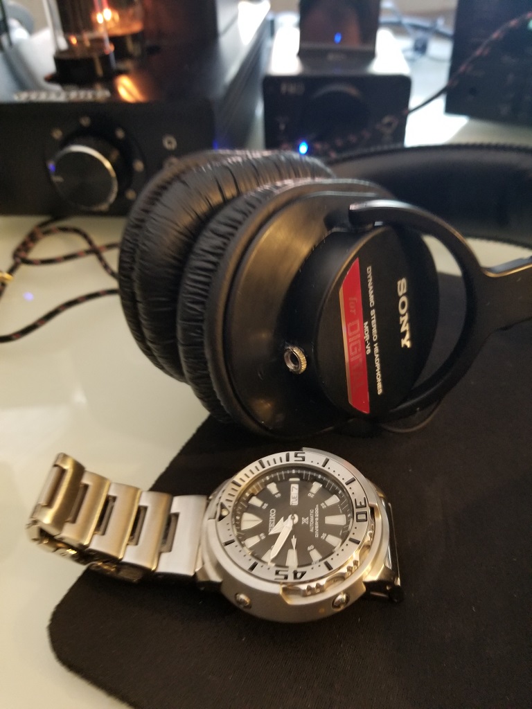
[size=24pt]SONY MDR-V6 REMOVABLE CABLE MOD[/size]
[size=medium]DISCLAIMER: Try it at your own risk[/size]
[size=medium]Components Required: [/size]
[size=medium] [/size]
[size=medium]IMPORTANT POINTS TO NOTE:[/size]
[size=medium]Also [/size]

[size=medium]STEP BY STEP INSTRUCTIONS:[/size]


[size=medium]Now the plastic portion of plastic cup goes inside the metal cup and hence adding additional thickness and hence making it difficult for the female chassis to be mounted on the inside of the metal cup. Hence, with help of Dremel tool you will have to grind out the excess plastic from the inside and outside of the metal cups for the chassis mount to sit tightly on the inside of the cups.[/size]
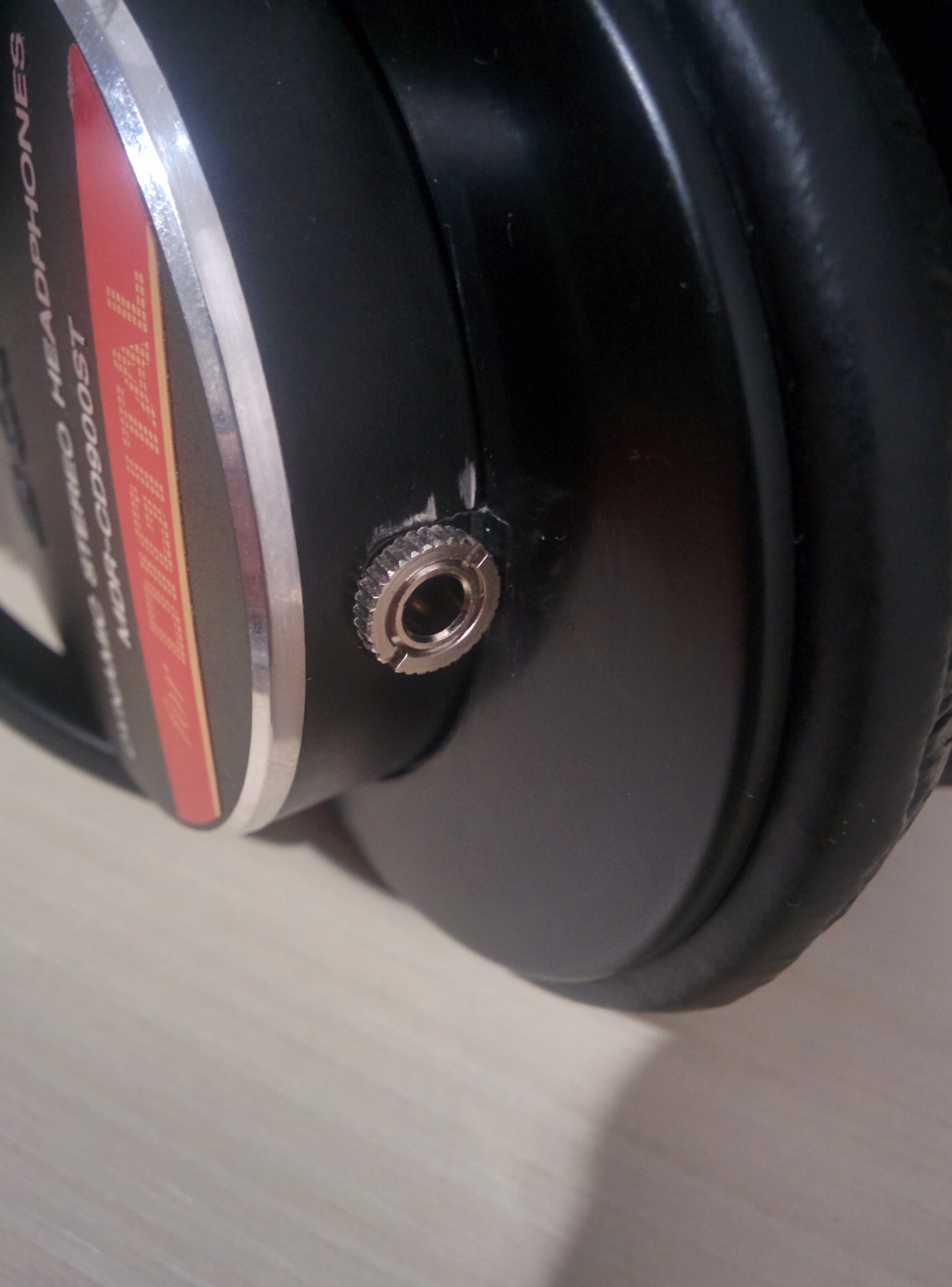
[size=medium]END PRODUCT:[/size]
[size=medium]This is my first attempt and it doesn’t look as bad as the picture, trust me. The scratches seen were made by the rough handling of Dremel tool. I more confident now and next time the finish should be much better") . By the way it sounds great and just waiting for the velour pads to arrive to test them properly.[/size]
. By the way it sounds great and just waiting for the velour pads to arrive to test them properly.[/size]
[size=medium] [/size]
[size=medium]DISCLAIMER: Try it at your own risk[/size]
[size=medium]Components Required: [/size]
[size=medium]
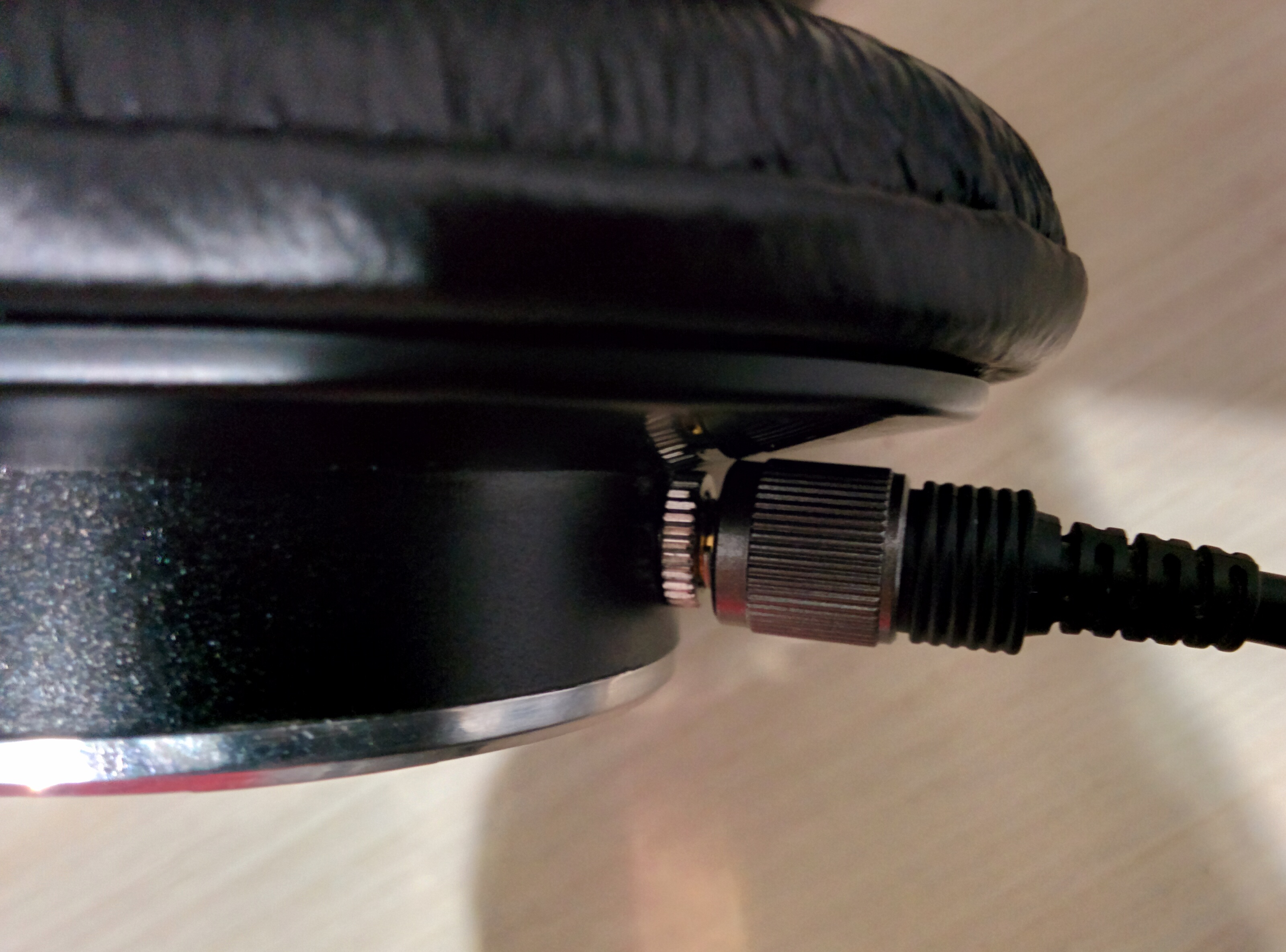
- [size=medium]3.5 mm Female Chassis Mount (Slimmest One available)[/size]
- [size=medium]Soldering Iron, solder, etc[/size]
- [size=medium]Dremel Tool[/size]
- [size=medium]Thin Wires[/size]
[size=medium]IMPORTANT POINTS TO NOTE:[/size]
- [size=medium]The width of the cup is very less, hence it is important to get the Slimmest female jack[/size]
- [size=medium]The portion from where cable comes out has a plastic mount, which needs to be sawed off otherwise the jack screw nut would not come out properly.[/size]
[size=medium]Also [/size]
- [size=medium]Also, the cup is metallic however the portion that holds the earpads is plastic. [/size]
[size=medium]STEP BY STEP INSTRUCTIONS:[/size]
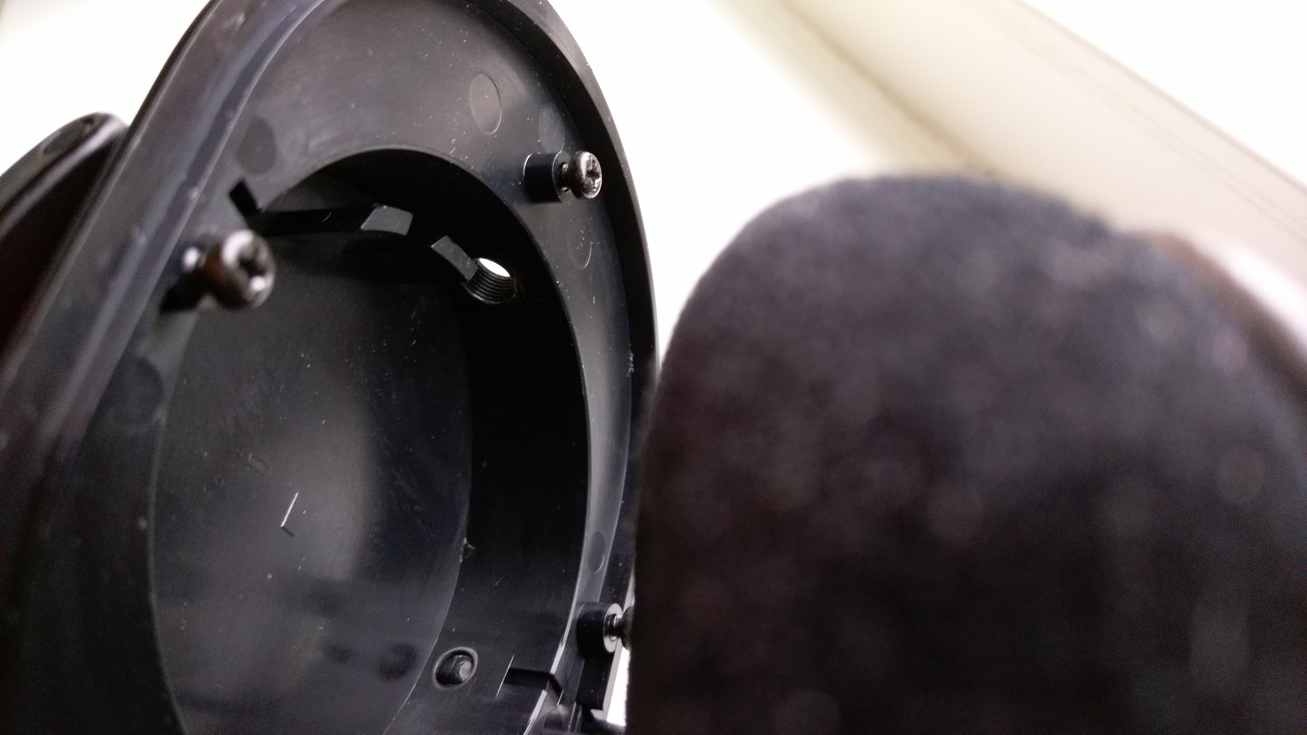
- [size=medium]Remove the earpads.[/size]
- [size=medium]Remove the four Philips screw carefully.[/size]
- [size=medium]You will see three cables; red, green and copper colored. They have to be connected in the following order.[/size]
- [size=medium]The cables inside MDR-V6 are different type which has insulation fiber like material on them which make it difficult to solder. When I tried first time. I cut the three colored wire at sufficient length, so that I had enough to work with. But when I soldered them they had gotten tangled and didn’t work. So I de-soldered the Red and Green cable off the driver magnet and instead used thin insulated copper cables. This worked [/size][size=medium]J[/size]
- [size=medium]Next thing to note is that the cups in MDR-v6 are made of metal however the flat part which holds the headband is made of plastic. To explain I have made a rough sketch:[/size]
[size=medium]Now the plastic portion of plastic cup goes inside the metal cup and hence adding additional thickness and hence making it difficult for the female chassis to be mounted on the inside of the metal cup. Hence, with help of Dremel tool you will have to grind out the excess plastic from the inside and outside of the metal cups for the chassis mount to sit tightly on the inside of the cups.[/size]
- [size=medium]When I tried first time, I tried to place the 3.5 mm chassis on the inside cup and then tried to solder which was difficult. The best way to do is to use a little additional wire and solder the connections on chassis mount before securing them to the inside of the cups.[/size]
- [size=medium]Lastly, since the cups are not deep enough, there is a possibility that the driver magnet touch the chassis mount and hence resulting in no sound. When I first completed soldering I was able to listen to the sound with the driver open but as soon as I closed it there was no sound. An easy work around that would be to place insulation tape on the driver so that there is no contact between the metal portion of the chassis and the driver magnet. This was a success.[/size]
[size=medium]END PRODUCT:[/size]
[size=medium]This is my first attempt and it doesn’t look as bad as the picture, trust me. The scratches seen were made by the rough handling of Dremel tool. I more confident now and next time the finish should be much better
. By the way it sounds great and just waiting for the velour pads to arrive to test them properly.[/size][size=medium]
anthony81212
100+ Head-Fier
- Joined
- Mar 27, 2006
- Posts
- 274
- Likes
- 11
Looks good! Gonna do it when mine arrives

wrathzombie
Headphoneus Supremus
- Joined
- Aug 16, 2011
- Posts
- 1,683
- Likes
- 138
Please be careful.
Keep the following things in Mind:
1. Your headphone might get destroyed/ aesthetically damaged. Please be prepared for that.
2. The Cup size in MDR-V6 is not much so you have to be very careful with the tools ( Drilling, filing soldering etc.)
3. You cannot use a thick 3.5 Male/Female Jack because of the cup size and try to get the slimmest ones possible.
If you are buying new headphones and planning to mod them, I would advice against it.
All the best
HiFi1972
100+ Head-Fier
- Joined
- Jan 30, 2009
- Posts
- 203
- Likes
- 56
Cool post! I also modded a pair of these a few months ago. I gave my son my V6's when he was around 4 years old. He beat them up real bad and stretched the wire going from the L cup to the R, and also messed up the stock cable by bending the 1/8" adapter while it was connected to a portable DVD player, so 6 years later, and after buying a few pairs of those "kids headphones" that have built-in attenuation, I decided to finally mod them, and wanted to make sure they would last abuse this time. I modded them to drop the signal about -10dB (used a 48 ohm wirewound resistor in series for each driver).
I used a similar female jack, it's slightly smaller than the one you used (found on eBay, a bit expensive but I wanted the smallest possible jack:
http://www.ebay.com/itm/New-3-5mm-Stereo-Socket-Connector-Round-Panel-Mounting-/390477206738?pt=US_Audio_Cables_Adapters&hash=item5aea4154d2
I also re-did the wire going from the L cup to the R cup with 22 awg wire and also shrink-tubed it. It still bends well enough to fold in the headphones, and after it was all done, I bought about 10 1/8" retractable connector cables for about $3. My kid already broke 3 of the cables, but the headphones are still alive and well. Here's a pic showing how mine turned out:
https://www.dropbox.com/s/6685n9gdn2u43kt/IMAG0234.jpg
I had a tiny scratch on my cup, I used a black sharpie marker to cover it up, and you can't tell there was a scratch at all.
wrathzombie
Headphoneus Supremus
- Joined
- Aug 16, 2011
- Posts
- 1,683
- Likes
- 138
Quote:
Awesome job !! You have done it much better than me ... This was my first attempt at modding, If I decide to mod something I would be better prepared.
Cool post! I also modded a pair of these a few months ago. I gave my son my V6's when he was around 4 years old. He beat them up real bad and stretched the wire going from the L cup to the R, and also messed up the stock cable by bending the 1/8" adapter while it was connected to a portable DVD player, so 6 years later, and after buying a few pairs of those "kids headphones" that have built-in attenuation, I decided to finally mod them, and wanted to make sure they would last abuse this time. I modded them to drop the signal about -10dB (used a 48 ohm wirewound resistor in series for each driver).
I used a similar female jack, it's slightly smaller than the one you used (found on eBay, a bit expensive but I wanted the smallest possible jack:
http://www.ebay.com/itm/New-3-5mm-Stereo-Socket-Connector-Round-Panel-Mounting-/390477206738?pt=US_Audio_Cables_Adapters&hash=item5aea4154d2
I also re-did the wire going from the L cup to the R cup with 22 awg wire and also shrink-tubed it. It still bends well enough to fold in the headphones, and after it was all done, I bought about 10 1/8" retractable connector cables for about $3. My kid already broke 3 of the cables, but the headphones are still alive and well. Here's a pic showing how mine turned out:
https://www.dropbox.com/s/6685n9gdn2u43kt/IMAG0234.jpg
I had a tiny scratch on my cup, I used a black sharpie marker to cover it up, and you can't tell there was a scratch at all
Awesome job !! You have done it much better than me ... This was my first attempt at modding, If I decide to mod something I would be better prepared.
anthony81212
100+ Head-Fier
- Joined
- Mar 27, 2006
- Posts
- 274
- Likes
- 11
Quote:
Excellent photography!
And the Sharpie trick is AMAZING, thanks for making my V6 look new again
https://www.dropbox.com/s/6685n9gdn2u43kt/IMAG0234.jpg
I had a tiny scratch on my cup, I used a black sharpie marker to cover it up, and you can't tell there was a scratch at all.
Excellent photography!
And the Sharpie trick is AMAZING, thanks for making my V6 look new again
chispa02
New Head-Fier
- Joined
- May 1, 2013
- Posts
- 5
- Likes
- 10
Thanks for the idea... I own a pair of old V7506 that the wire going from the L cup to the R is broken, so anyway I need to open and repair them.... sounds like a good time to do this mod...
Any recommendations on which cable should I use to rewire them from L to R?
Any recommendations on which cable should I use to rewire them from L to R?
AUDIOBREEDER
Headphoneus Supremus
- Joined
- Nov 12, 2012
- Posts
- 1,596
- Likes
- 92
Is it possible to connect a remote cable via. this approach?
razorblader
100+ Head-Fier
- Joined
- Nov 14, 2009
- Posts
- 213
- Likes
- 37
Is it possible to connect a remote cable via. this approach?
Yes.
Boom Shaka Laka
Head-Fier
- Joined
- Oct 25, 2005
- Posts
- 85
- Likes
- 10
ok, good mod idea, but practically speaking do you get easy kick outs as the mini connector faces downward and it wouldn't take much tug on cable. A screw in connector or some locking type would be better although may not have the dimensions to make it work from the same cup spot.
Enyawd72
New Head-Fier
- Joined
- Feb 6, 2014
- Posts
- 1
- Likes
- 10
could i just mod the cable by cutting and reattaching it to a cut of stand alone female cable
KElyas
100+ Head-Fier
- Joined
- Sep 5, 2012
- Posts
- 212
- Likes
- 11
could i just mod the cable by cutting and reattaching it to a cut of stand alone female cable
I'm also interested in this. Did you find an answer?
phamtasm
Head-Fier
- Joined
- May 21, 2012
- Posts
- 55
- Likes
- 10
could i just mod the cable by cutting and reattaching it to a cut of stand alone female cable
I'm thinking this is an easier way to go as well. Anyone out there with info on this?
mark42na2
New Head-Fier
- Joined
- Aug 15, 2014
- Posts
- 2
- Likes
- 0
Here's my mod although it's a 7506.


afxdave
100+ Head-Fier
- Joined
- Feb 13, 2004
- Posts
- 199
- Likes
- 11
Hey all,
Here's one a did a few years back. Mouser sells some decent 3.5mm connectors that fit securely:
http://www.mouser.com/ds/2/253/KC-300961-196008.pdf


Sorry for not having any interior shots, but some really good sueprglue, or epoxy is enough to hold the plastic in place. The bond is secure since it's two plastic surfaces adhering together.
Here's one a did a few years back. Mouser sells some decent 3.5mm connectors that fit securely:
http://www.mouser.com/ds/2/253/KC-300961-196008.pdf
Sorry for not having any interior shots, but some really good sueprglue, or epoxy is enough to hold the plastic in place. The bond is secure since it's two plastic surfaces adhering together.
Users who are viewing this thread
Total: 2 (members: 0, guests: 2)
