SOHA II Builders Thread
Nov 9, 2008 at 6:34 PM Post #106 of 1,694
Quote:

Don't have my ultrasensative M-Audio Q40 around to test with higher impedence, but I plugged in one of my 16-ohm IEMs (Crossroads MylarOne X3) which are quite sensitive as well and I have a hiss too. I don't notice it with my other sensitive cans, like the ATH-ANC7 and the K81DJ.

I recall checking this with the old B+ (pre-HV) config, and I recall not noticing this, but that was also before casing when it was sitting out on my desk.

I'll see what I can find out tomorrow, if I have time. I will try to isolate the buffers first.

I have a scope, but my 200MHz probes are broken. I think I have some 400MHz probes around somewhere, but I haven't used my 400MHz unit plugin so I'm not sure if it's functional.

If I can measure, I will. What would you like done?

With the protoboards we have, we should just be able to disconnect the external HV perfboard as well, if you don't want to desolder C1/C2 and you put terminals on. At least, I think that'll work.

Edit: I hear it with my DT660, but it's slight.


Hiss is pretty hard to see on the scope because it's just noise on the trace.

But, it's worth looking at the LV+ and LV- rails to see if there is noise on them. And then the base of Q5 and the O/P of the buffers. If there is visible noise on the traces then check whether it's larger at the O/P than it is at Q5. If it is, the buffer is introducing noise. If not the noise is coming from before the buffer.

The only way the buffer can introduce noise is either noise on the rails or just plain noise generation in the components. Every element in the circuit makes some amount of noise, especially the BJTs. But there are a few zillion O/P buffers out in the world and most of them don't create additional audible noise.

Edit: I missed Ferrari's post when I wrote this, but those are important things to check out too. And I see that Ferrari has already checked out the noise from the buffers and found it neglible.
 
Nov 9, 2008 at 11:45 PM Post #108 of 1,694
@ runeight

A newbie Q i apologise if this makes no sense but i'm trying to teach myself electronics here goes: as i have HD650's and only ever listen a very tame levels i find the gain on my earmax pro too high so dont really get much scope volume wise, Now if I were to use very linear tubes with high gain characteristics say 12at7's and then increase the negative feedback to reduce gain would the amp be more linear than say 12au7 with standard negative feedback?? does that make sense??
 
Nov 10, 2008 at 12:15 AM Post #109 of 1,694
Theoretically yes the higher gain tube would be more linear if its gain were substantially reduced by the NFB.

Practically speaking, however, this is almost never true. NFB always involves some amount of phase shift as the signal returns from the output to the input (or wherever it is injected). This means that the cancellation signal can be slightly out of phase with the signal it's supposed to cancel. This phase shifting causes other modulation products such as intermodulation distortion that add other harmonics to the signal and, audio-wise, make the sound worse.

Some amps (like the beta22) are designed with such high speed and small phase shift that they can support what I consider to be large amounts of NFB and still be extremely audio clean.

Most average amps cannot support large amounts of NFB and still sound good. In this case the better choice is to start with lower gain and either have no NFB or only a modest amount.

The SOHA II, for example, has only about 6db of NFB. Just enough to reduce the gain for all tubes to a tolerable range and to reduce the THD without introducing too many sloppy harmonics into the mix.

On a side note, opamps running in unity gain mode as buffers (which is the way many amps use them) have infinite NFB and this is the reason, IMHO, why they don't often sound as good as discrete buffers that have no NFB. Opamp amps where the gain is set to something reasonable with NFB also must use very high NFB to achieve low gain and, IMHO, still an audio issue. This last category includes some of the opamp based amps that are being built by headfiers (but not all of them).
 
Nov 10, 2008 at 12:23 AM Post #110 of 1,694
Quote:

Originally Posted by Ferrari /img/forum/go_quote.gif
I have looked at the instrinsic noise of the output buffer (more than once) during the prototyping phase and it is very low, so I’m quite sure that it’s not likely that the noise is coming from there.

Take a closer look at the wiring of the input => volume pot => PCB, all these wires are unshielded and the distance is quite long. Pure from technical point of view, this can’t be healthy for the very sensitive input signal.
wink.gif


That's good to know, Ferrari. My signal lines are shielded till it hits the PCB (didn't run it directly to the pot). The rest is unshielded. The hiss is there regardless of knob, so it's post-attenuator. There is some additional noise pre-attenuator, but it's characteristic is slightly different, and it's at knob positions I will never hit (75% and higher).

I do know I have an issue. I knew it when I routed the power lines on my build, but I was hoping there would be no issues. I will re-route.

Quote:

Originally Posted by runeight /img/forum/go_quote.gif
But, it's worth looking at the LV+ and LV- rails to see if there is noise on them. And then the base of Q5 and the O/P of the buffers. If there is visible noise on the traces then check whether it's larger at the O/P than it is at Q5. If it is, the buffer is introducing noise. If not the noise is coming from before the buffer.


I'll look another day. My back is hurting and I can't bend over this thing any longer.

FWIW, I knew I had some wiring problems when I initially did it. I have 1/8" spacers and I routed the AC lines back to front under the PCB. I figured I would redo it if I hit some issues. I redid them routing around the PCB, and I disconnected the B+ from where the perfboard runs into the PCB (terminal block) and the hiss reduces dramatically. With the tubes out but B+ in place, it's still there....and I have a bit of a buzz. The buzz reduces, when I pull the LED plug (terminal block). That is definitely wiring issues, with the LED for the switch, definitely. Kind of hard to route, since I have 1/8" spacers and amost no room side to side without crossing over my stepped attenuator or going under the PCB. Anyhow, the buzz doesn't concern me much.

I think I'm getting noise in from the B+...but that can also mean that my AC lines inherently have noise. I didn't put a pi, CLRC filter, or any of the commercial filters in line from my wallwart. I probably should have.
 
Nov 10, 2008 at 12:39 AM Post #112 of 1,694
It's really hard to tell with issues like this exacty what the cause is. It is possible that the new style B+ supply is adding more noise than before. I built a proto version of the new B+ supply and used it for a while to test it out. My headphones may not be as sensitive as others, but in my case I didn't hear any increase in noise. That is, the amp was as quiet as before with the original supply.

So, for the moment, I don't know . . .

Ferrari, aren't you using a perf version of the B+? Is there additional noise?
 
Nov 10, 2008 at 3:00 AM Post #113 of 1,694
Quote:

Originally Posted by runeight /img/forum/go_quote.gif
Ferrari, aren't you using a perf version of the B+? Is there additional noise?


I alos had some noise issues with the perfboard version of the HVPS - but I was embarrased to find (what I thought) was the probelm when I redid the B+ with KKLees PCB version - a bad RCA cable jack solder joint.

My amp is near silent now with the PCB HVPS - perhaps there was some noise I hadn't attributed correctly. I have some 32R phones on the way and will give another listen -although I'm not sure I am willing to hook the perfboard HVPS back up to A/B
wink_face.gif
 
Nov 10, 2008 at 6:26 AM Post #114 of 1,694
Quote:

Originally Posted by runeight /img/forum/go_quote.gif
...
Ferrari, aren't you using a perf version of the B+? Is there additional noise?


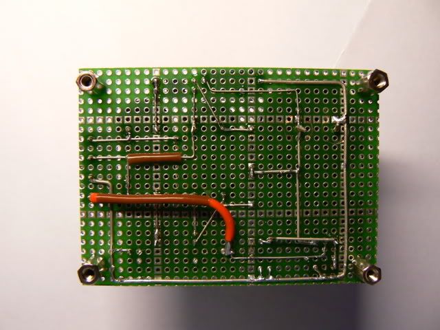
Botchery constructed HV B+ PS on perfboard can induce noise into the audio circuit of the amp.
With my initial clumsy spaghetti style 95V B+ PS I did got some serious noise.

I then re-work my 95V B+ PS as depicted in the picture below, with more attention to the layout (keep AC traces as far as possible from DC traces, solider ground path…), my B+ works properly, without any audible noise.

Afbeelding583.jpg


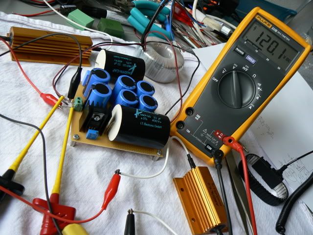
The 120V B+ PS (for my GF amp) has got a similar layout and works very well, without noise.
smily_headphones1.gif


Afbeelding536.jpg
 
Nov 10, 2008 at 1:18 PM Post #115 of 1,694
Quote:

Originally Posted by Ferrari /img/forum/go_quote.gif
Well done GeWa. Looks like you are not going to come in as last.
icon10.gif

Now testing and listening. Enjoy!


No, he's definitely not going to come in last
redface.gif


I've ended up short of few parts - doh! Forgot to order C5 and for some strange reason I ordered only 1 each of the 10R and 200R trimpots. And I also don't have a suitable part for the relay. I bought two different parts from Rapid, one is only half the size and the other is the right size but the coil sensitivity is 200mA.

I've also not mounted the tube sockets as I'm still debating whether to 'air mount' them, mostly because I'm not confident I'll be able to drill the top holes in the enclosure in the right place to line up with the pcb.

But I'll keep you posted on progress
smily_headphones1.gif
 
Nov 10, 2008 at 5:38 PM Post #116 of 1,694
Uncle Bob have you looked at the drilling templates on the website? There is one for the front panel and one for the top panel. Using these dimensions should line up all of the holes properly.
 
Nov 10, 2008 at 8:39 PM Post #117 of 1,694
Quote:

Originally Posted by runeight /img/forum/go_quote.gif
Uncle Bob have you looked at the drilling templates on the website? There is one for the front panel and one for the top panel. Using these dimensions should line up all of the holes properly.


LOL, I was referring to my inability to drill a hole in the right place - I had seen your templates on the website and I intend to make use of them, for the front panel certainly, but I am famously cack-handed when it comes to anything involving measuring, cutting or drilling.

I'm considering buying a drill stand, hopefully that will make things a little less error-prone, but then again it's more expense..
 
Nov 10, 2008 at 9:31 PM Post #118 of 1,694
Quote:

Originally Posted by GeWa /img/forum/go_quote.gif
Haven't tested it yet because of being busy for work!!! Correct about the transistors, I'm using the 2SC2238.
According to Ferrari they should work also.

Regards


Take the necessary time to walk through the initial setup… step by step. You will get your amp playing music soon.
smily_headphones1.gif

With these Toshiba output devices, I’m sure you will like it.
 
Nov 10, 2008 at 10:34 PM Post #119 of 1,694
Quote:

Originally Posted by Uncle Bob /img/forum/go_quote.gif
I'm considering buying a drill stand, hopefully that will make things a little less error-prone, but then again it's more expense..


Full size templates are a great help, printed out to the right size and mounted on thin (file folder) card stock. Then a punch with a steady hand to mark the hole and guide your step bit (you do have a step bit don't you?
regular_smile .gif
)

I have been able to do quite nice work by hand this way.
 

Users who are viewing this thread

Back
Top