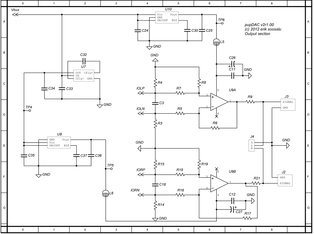
pupDAC Step-by-Step Build Thread
Mar 7, 2014 at 7:54 PM Post #196 of 359
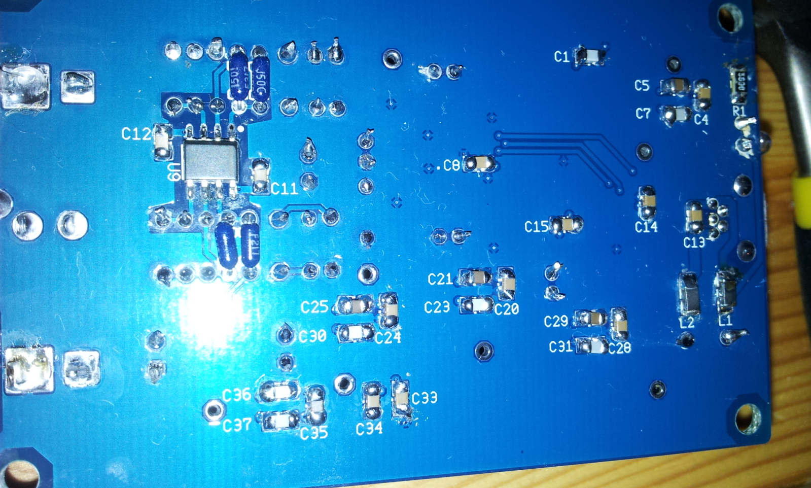
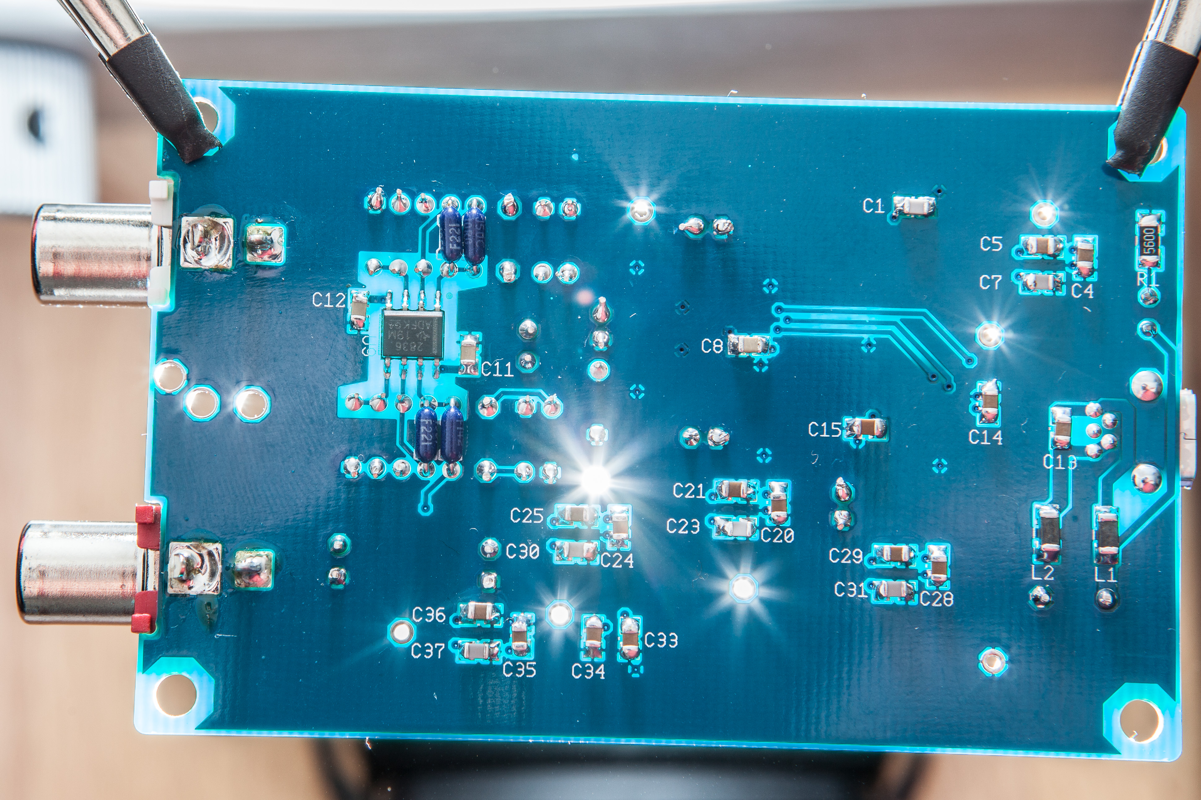
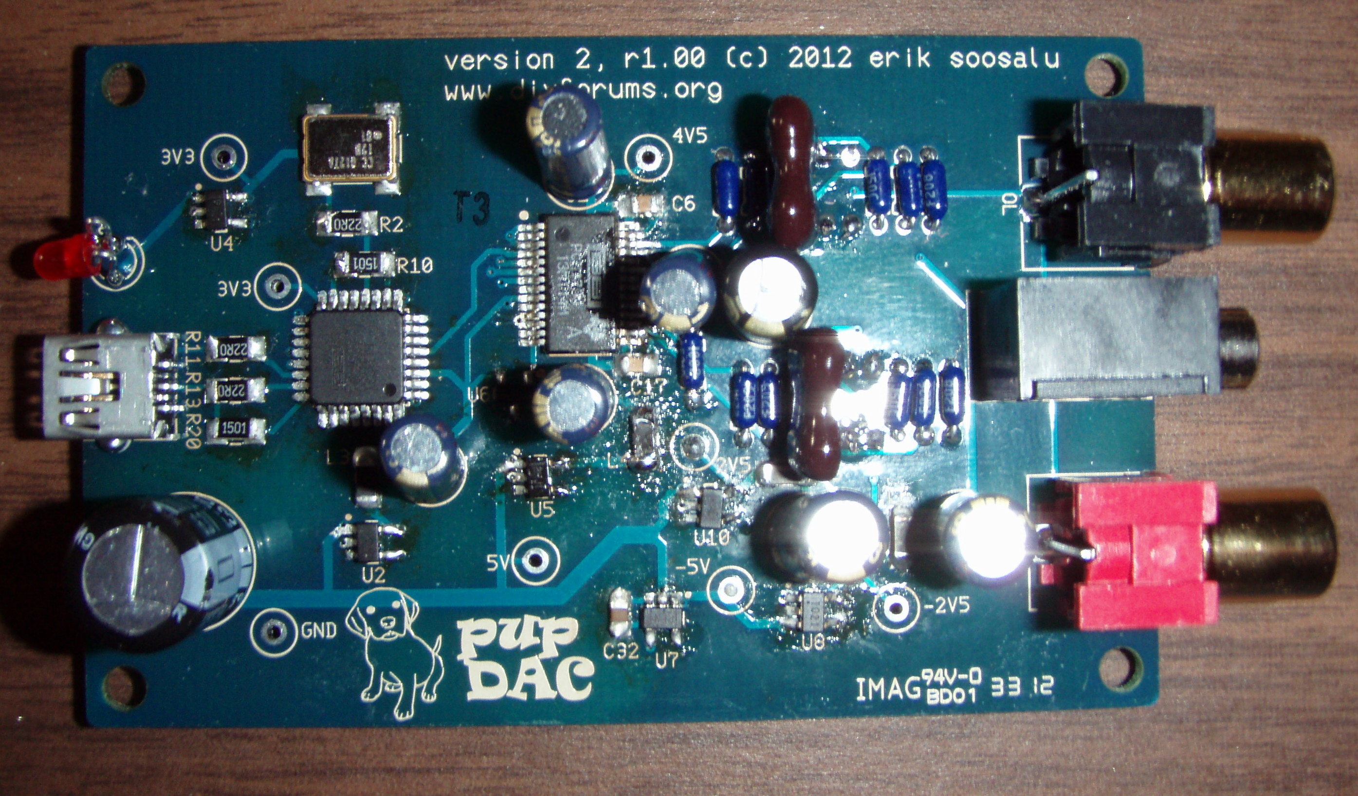
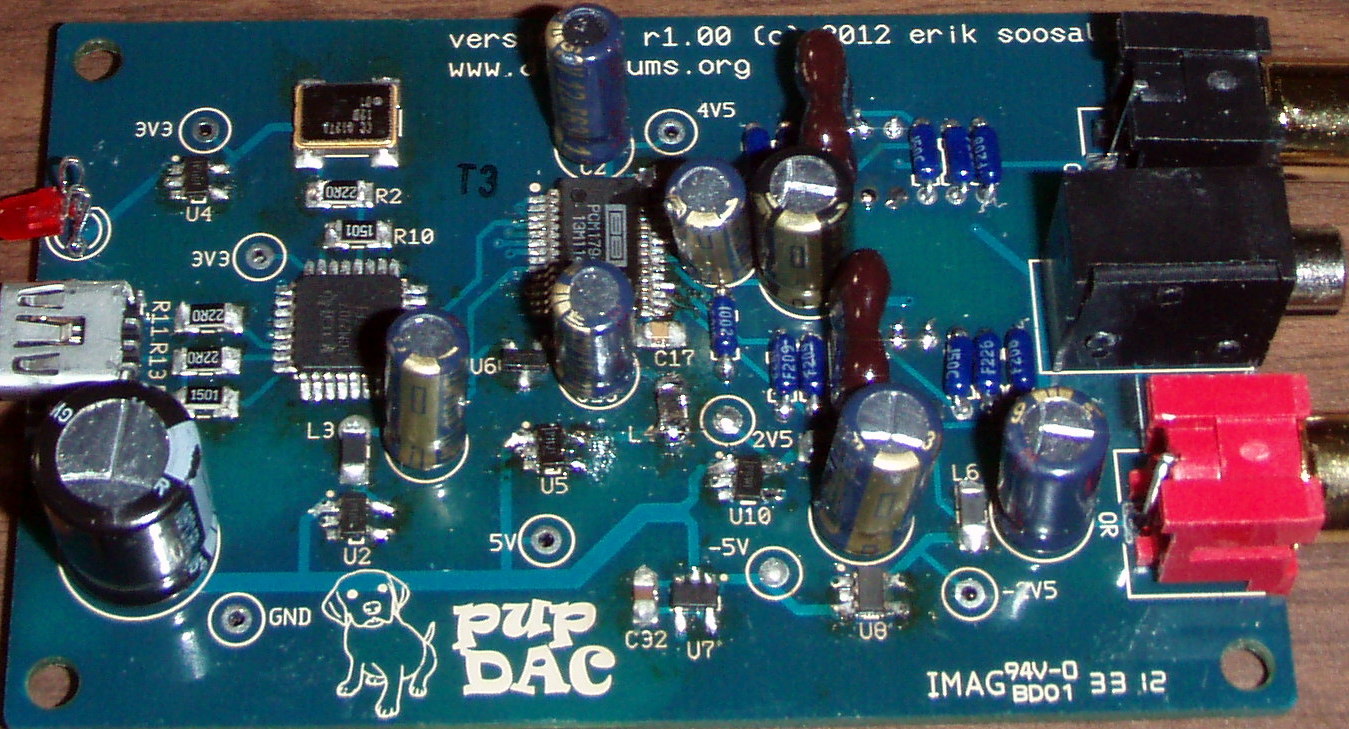
How long can and or should the board be soaked in alcohol for to get the flux off?


  I don't soak boards, just lay into it with an old toothbrush and blot dry with a wad of tissues, do that twice and all the flux will be gone
 
cheers
FRED


Neither of these is really a contradiction and I agree with both.  Soaking a board is fine - as long as everything is truly a solid-state component.  Once you add electrolytic capacitors or other "physical" components, though, you have to use the toothbrush and blot dry with paper towels/equivalent.*  Electrolytics are an easy justification - they have a liquid electrolyte inside and are not necessarily completely water-proof.  At the same time, physical components such as switches and pots - volume and otherwise - may have grease in them to promote easy physical interaction.  This can be destroyed if you soak a PCB with those components on it.
 
I am careful in my build instructions that a total immersion of a PCB is only possible at a certain stage in the construction - not any further.
wink.gif


* One caveat - I've had many larger boards that may take as many as half-a-dozen rinses or more with a toothbrush and paper towel blot before the flux is significantly removed.  That may just be me and the type of soldering I do, though.
 
Mar 7, 2014 at 10:12 PM Post #197 of 359
Sorry, I should have been more specific with my question.  Your guide is excellent!  I am done soldering on all the SMD components, so I am at that point in your guide when you say to soak the board.  I went at it with a new toothbrush a couple of times and a few minute soak but still have some flux left on the board.  It's pretty clean but it didn't all come off.  I'm just going to let it dry out and continue on.
 
By the way at the bottom of this page of the picture guide, above the last pic on the page, it says "Finally, there are three 1206 ferrites on the top side.", but there are four ferrites on the top, not three.  Also, the pic is a little misleading, since you just mentioned ferrites, I would think the arrows should be pointing to the ferrites, not some caps.  One more thing, the last text on that page says "You've now finished all the SMD parts on the top side of the PCB!", but the pic does not show all the SMD parts on the top soldered.  Again not a big deal just a bit misleading.  I'm not complaining, just offering some feedback on how to make it better!  Your guides are great and much better than most other DIY projects I've come across.
 
Mar 7, 2014 at 10:24 PM Post #198 of 359
  Sorry, I should have been more specific with my question.  Your guide is excellent!  I am done soldering on all the SMD components, so I am at that point in your guide when you say to soak the board.  I went at it with a new toothbrush a couple of times and a few minute soak but still have some flux left on the board.  It's pretty clean but it didn't all come off.  I'm just going to let it dry out and continue on.
 
By the way at the bottom of this page of the picture guide, above the last pic on the page, it says "Finally, there are three 1206 ferrites on the top side.", but there are four ferrites on the top, not three.  Also, the pic is a little misleading, since you just mentioned ferrites, I would think the arrows should be pointing to the ferrites, not some caps.  One more thing, the last text on that page says "You've now finished all the SMD parts on the top side of the PCB!", but the pic does not show all the SMD parts on the top soldered.  Again not a big deal just a bit misleading.  I'm not complaining, just offering some feedback on how to make it better!  Your guides are great and much better than most other DIY projects I've come across.


1. You're fine on what you did with the soak.
 
2. Yes, you're sharp in noticing that.  I noticed it myself awhile back, then forgot to correct it.  If memory serves, you might look back through this very thread and see that it's correct, but that I copied it incorrectly on the website.  The Step-By-Step guide on the website is probably more technically correct than the "Build-by-Photo."  I'll see if I can correct it this weekend.
redface.gif

 
Mar 8, 2014 at 6:08 AM Post #199 of 359
Cool thread, thank you tomb for taking the time and energy to make a step by step, it really gives the urge to newbies like myself to give this build a shot.
 
Mar 9, 2014 at 1:54 AM Post #200 of 359
Finished the board tonight.  The step-by-step guide w/ pics is amazing and makes this project easy.  Make sure you follow tomb's advice.
 
Decent tweezers are a must for all of the SMD work, I used the curved tip ones from this set and they worked great.
 
When soldering some of the chips with the drag-n-wipe method, you might swipe some solder into an adjacent through-hole (I did this when soldering the op-amp on the bottom side).  No big deal, just use some solder-wick to clean it up.
 
Checking all of your solder joints (particularly the SMD work) with a high power magnifying glass is a MUST.  I used the 10x spot lens on this magnifying glass extensively to check my work (although something with 10x magnification that had a bigger lens would've been nice).  Checking the chip solder joints in the bright sun is a great way to identify any problems.  I soldered the top two chips one night and waited until the day after to check them in the sun.  I'm glad I did because I saw a couple more bridges that I didn't see the night before.
 
Once past all the SMD work, the through-hole stuff goes quick.  I still need to do the final flux cleaning, but I went ahead and plugged it into my Mac and all the voltages checked out okay.  The DC offsets at the output jacks were 0mV and 1.1mV, so I'm good there.  I checked all the other voltages at the test points and every one was within 0.02V except for the 4.5V one, mine tested at 4.72V.  Is that okay?  The pupDAC was identified fine by my Mac.
 
Would the DC offset at the output jacks be any different when playing music and/or when having the computer volume turned up all the way?  Meaning should I test under those conditions as well?  How about when using it with different computers?
 
Mar 9, 2014 at 10:17 AM Post #201 of 359
  Finished the board tonight.  The step-by-step guide w/ pics is amazing and makes this project easy.  Make sure you follow tomb's advice.
 
Decent tweezers are a must for all of the SMD work, I used the curved tip ones from this set and they worked great.
 
When soldering some of the chips with the drag-n-wipe method, you might swipe some solder into an adjacent through-hole (I did this when soldering the op-amp on the bottom side).  No big deal, just use some solder-wick to clean it up.
 
Checking all of your solder joints (particularly the SMD work) with a high power magnifying glass is a MUST.  I used the 10x spot lens on this magnifying glass extensively to check my work (although something with 10x magnification that had a bigger lens would've been nice).  Checking the chip solder joints in the bright sun is a great way to identify any problems.  I soldered the top two chips one night and waited until the day after to check them in the sun.  I'm glad I did because I saw a couple more bridges that I didn't see the night before.
 
Once past all the SMD work, the through-hole stuff goes quick.  I still need to do the final flux cleaning, but I went ahead and plugged it into my Mac and all the voltages checked out okay.  The DC offsets at the output jacks were 0mV and 1.1mV, so I'm good there.  I checked all the other voltages at the test points and every one was within 0.02V except for the 4.5V one, mine tested at 4.72V.  Is that okay?  The pupDAC was identified fine by my Mac.
 
Would the DC offset at the output jacks be any different when playing music and/or when having the computer volume turned up all the way?  Meaning should I test under those conditions as well?  How about when using it with different computers?

 
Thanks for the kind comments!

4.72 is fine.  The regulator in that part of the circuit actually regulates to 4.75.  A few hundredths off can be attributed to the meter and other variances.  I think cobaltmute simply did want to take up the room on the PCB by using 3 digits with the silkscreen.
wink.gif
 
 
As for your last question, no, the offset will not change under differing conditions.  One note, though - you should always have the volume turned up all the way on whatever media player you're using.  Otherwise, it will start interpolating bits to lower that volume and you'll actually lose some data integrity and quality.  That doesn't apply to the computer volume, unless the PupDAC becomes the default media device and you're using the OS volume control to reduce volume.  The only way you should be reducing volume through the PupDAC is with an amplifier.  An exception to that might be if you're using IEMs plugged directly into the PupDAC, but then that's a somewhat compromised scenario, anyway.  Still, I've gotten great results doing that, but it would probably still work better if you went through some sort of amplifier.
 
I always recommend Foobar2000, because it lets you choose the music source separately from the computer's OS.  I'm not sure about a Mac, though, so YMMV.  
 
Mar 10, 2014 at 9:04 PM Post #202 of 359
I just assembled my kit. The mac did recognize it as DAC, but when I connected it to a earbud, the music was played through earbud in maximum volume(at least it's loud) and I can't change the volume through mac. I checked the voltage as follows:
3V3: 3.297V
5V: 5V
4V5: 4.76V
-5V: 0.429V
-2V5: 0.59V
offset:0.588V
 
Could anyone please give some insight on where to debug?
 
Mar 10, 2014 at 9:46 PM Post #203 of 359
  I just assembled my kit. The mac did recognize it as DAC, but when I connected it to a earbud, the music was played through earbud in maximum volume(at least it's loud) and I can't change the volume through mac. I checked the voltage as follows:
3V3: 3.297V
5V: 5V
4V5: 4.76V
-5V: 0.429V
-2V5: 0.59V
offset:0.588V
 
Could anyone please give some insight on where to debug?

Well, I would've said the MAC's OS, but you have an issue at the 2.5V test point.  If you're only measuring 0.59V, then something is wrong.  Check all the pins around U10.  Make sure they're clear of bridges and have good connections to the pads.
 
Mar 10, 2014 at 10:15 PM Post #204 of 359
 
Could anyone please give some insight on where to debug?


I'd check U7 for shorts and opens.
Also C32, C33 and C34.
Your whole negative rail is not functioning.
Re-flow if necessary
 
If all else fails, replace U7
 
Mar 10, 2014 at 10:36 PM Post #205 of 359
 
 
Could anyone please give some insight on where to debug?


I'd check U7 for shorts and opens.
Also C32, C33 and C34.
Your whole negative rail is not functioning.
Re-flow if necessary
 
If all else fails, replace U7


Correct, as usual.  For some reason, I was reading his .429V as close to -5V.
wink.gif
 
 
Mar 13, 2014 at 10:11 AM Post #206 of 359
 
I'd check U7 for shorts and opens.
Also C32, C33 and C34.
Your whole negative rail is not functioning.
Re-flow if necessary
 
If all else fails, replace U7

Thanks Avro! It turned out the output from U7 is not making contact with the board. I put a little bit solder on that leg and now every point gets the right value. Anyway, thank you!
 
Mar 15, 2014 at 7:06 PM Post #208 of 359
  From what I'm seeing in this tutorial, the enclosure does not seem to be grounded to the USB shield. Any reason for this? Would there not be improvements from earthing the case?


The shield from the USB cable and the connector metal are grounded through the USB buss.  JMHO, but there's a heckuva lot more metal in a PC chassis than the little aluminum PupDAC case.  In comparison, the case is kind of trivial.
 
Apr 14, 2014 at 9:43 PM Post #209 of 359
Another little Pup is born!
 
Finished putting this together this afternoon and spent the evening, night, and wee hours listening to all sorts of music though it. I have to say i am deeply impressed, it handled everything i threw at it with aplomb.  I am running it through a USB Isolator/Linear regular i built for my ODAC, though the Doodlebug is my next project.
 
Vs the ODAC i found a few differences, the high end is sweeter and more refined, and the mid to low end has a lovely energy to it. Where the ODAC can sometimes sound flat and lifeless this little Pup has a bigger pair of lungs and handles dynamic shifts much better.  I dont know how they compare on stats like THD, distortion, crosstalk etc and to be honest i don't really care, all i know is it sounds better to me.  Only downside i can see is the limitation of the USB interface, 24bit would be nice to have, not that i have much 24bit material anyway.
 
I had intended to use this DAC with a portable valve amp as my music rig for work but i cant see myself unplugging it from my S.E.X. amp any time soon.  This really is an awesome little DAC, nice work Tomb!
 
Apr 15, 2014 at 10:21 AM Post #210 of 359
Hey guys,
 
I built a GrubDAC a while back and it sounds great. However, my one gripe with it was that Windows 7 didn't like it all too much. If I wanted to change the volume, I had to go into the advanced mixer and change the volume on each program separately. I could not simply pull the master volume up or down, which also made using an Fn+key volume shortcut useless. 
 
Does the PupDAC suffer from the same problem? I'm planning on using it with Windows 8 in the even that I build one. I guess I should also ask, does the GrubDAC still have this problem on Windows 8?
 
Thanks.
 

Users who are viewing this thread

Back
Top