PPAS Build Thread.
Jul 4, 2006 at 1:28 PM Post #46 of 254
Are there no other similar buffer chips with output like a Buf634 ? I looked at the LM6171, 6172, and 7171 and while fast, their outputs are limited to arround 100mA compared to the 250mA of the hard to get Buf634.

I'd enjoy hearing some feedback as to the sound when some of you finish.
 
Jul 4, 2006 at 3:52 PM Post #47 of 254
Oz - the other buffer we are discussing is the National LMH6321. Pretty much your only other option for a buffer is a DIY discrete arrangement. Cetoole and ATAT devised a compact arrangement in the PPAS development thread that I intend to implement on one of my PPAS boards. The discrete buffer will come later, just want to ensure correct operation with the IC buffers before I attempt discrete. I'm not a huge fan of the buf34 sound and they are impossible to get in SOIC format right now, so I will attempt an LMH6321 config when my parts all show up.

Edit
rsabo - the one jumper is connected to all three buffers' BW pins so that jumper will function to place all 3 buffers in high BW mode. If you are looking at the board or board artwork, it is the 2 oval shaped pads to the left of BUFR. I believe you could also place a resistor here like pimeta R11, but the drilled pads allow you to hook up wires for a switch to that high BW can be turned off to save battery life.
 
Jul 4, 2006 at 4:10 PM Post #48 of 254
Quote:

Originally Posted by quicksilver96
Oz - the other buffer we are discussing is the National LMH6321. Pretty much your only other option for a buffer is a DIY discrete arrangement. Cetoole and ATAT devised a compact arrangement in the PPAS development thread that I intend to implement on one of my PPAS boards. The discrete buffer will come later, just want to ensure correct operation with the IC buffers before I attempt discrete. I'm not a huge fan of the buf34 sound and they are impossible to get in SOIC format right now, so I will attempt an LMH6321 config when my parts all show up.


Plus the HA3-5002 adapters, that yours truly designed.
Speaking of, ATAT, are you planning on selling those? Just so I know.

I also see how the jumpers work now, but what is the effect when a resistor is used instead of a jumper? In the PIMETA, where R11 is used to set the bandwidth, each buffer has it's own jumper. Using a resistor in place of a straight jumper allows you to control the amount of quiescent current, but what happens when three buffers share the same resistor?

EDIT: Man it took me a while to write that out. Thanks anyway quicksilver.
EDIT2: oops, credited wrong guy
 
Jul 4, 2006 at 5:09 PM Post #49 of 254
Looking at the schematic from the data sheets, it would appear that BW limiting is done by adjusting a current, I.1, to V- by interjecting a parallel resistance with a 4K resistor and the V- plane via the BW pin. Even by tying these BW pins together (J1 still open), the design has effectively put all 3 of the 4K resistors in parallel between the current source and V- so the bandwidth is increased even without a resistance or straight connection present in the J1 location!

On a Pimeta, the 220 ohm R11 will go in parallel with 1 internal 4K ohm resistance for an equivalent of 208ish ohms (there is a 150 ohm internal resistance in series with the 4K/BW resistance as well). With the PPAS we already have reduced the 4K/BW resistance to roughly 1333 ohms so to achieve the equivalent of the 208 ohms on the pimeta, a 247 ohm resistor can be placed across J1 to achieve this value.

I'll post up my schematics in a sec so someone can double check me.

BUF634WB.jpg
 
Jul 4, 2006 at 5:31 PM Post #50 of 254
Quote:

Originally Posted by quicksilver96
Looking at the schematic from the data sheets, it would appear that BW limiting is done by adjusting a current, I.1, to V- by interjecting a parallel resistance with a 4K resistor and the V- plane via the BW pin. Even by tying these BW pins together (J1 still open), the design has effectively put all 3 of the 4K resistors in parallel between the current source and V- so the bandwidth is increased even without a resistance or straight connection present in the J1 location!

On a Pimeta, the 220 ohm R11 will go in parallel with 1 internal 4K ohm resistance for an equivalent of 208ish ohms (there is a 150 ohm internal resistance in series with the 4K/BW resistance as well). With the PPAS we already have reduced the 4K/BW resistance to roughly 1333 ohms so to achieve the equivalent of the 208 ohms on the pimeta, a 247 ohm resistor can be placed across J1 to achieve this value.

I'll post up my schematics in a sec so someone can double check me.


So if I'm reading the graph correct, that means by default, with an open J1, the BUF is running at around 4mA. Also, putting just a jumper in J1 does nothing, because according to tangent's calculator (I don't know the formula for parallel resistors) adding 0 ohms to the 3x 4k does nothing.
 
Jul 4, 2006 at 5:34 PM Post #51 of 254
Incorrect, adding a jumper reduces the resistance to zero rather than 1333 which it is currently. Go to the calculator and put 1 ohm in rather than 0, tangent must have some code that prevents a nil entry from effecting the calculation. Anything in parallel with 0 ohm is 0 ohms.

I'm not sure that just jumpering J1 is the best course of action as well. This is from tangent's site:
According to tests by KurtW and others, distortion drops as bandwidth goes up, though once R11 falls below about 200 Ω, distortion starts rising again.
 
Jul 4, 2006 at 5:44 PM Post #52 of 254
Quote:

Originally Posted by quicksilver96
Incorrect, adding a jumper reduces the resistance to zero rather than 1333 which it is currently. Go to the calculator and put 1 ohm in rather than 0, tangent must have some code that prevents a nil entry from effecting the calculation. Anything in parallel with 0 ohm is 0 ohms.

I'm not sure that just jumpering J1 is the best course of action as well. This is from tangent's site:
According to tests by KurtW and others, distortion drops as bandwidth goes up, though once R11 falls below about 200 Ω, distortion starts rising again.


Yeah I read that on the parts info page. I also saw my error when I looked up what the formula is and realized that I would have to divide 1 by zero. I'll get this "electronics" gig eventually.
 
Jul 5, 2006 at 1:00 AM Post #53 of 254
First things first..

the discrete buffer board and HA3-5002 adaptors *will* be made, but its been put off for a while now, and that may continue for a bit.. I cant possibly see enough demand to justify a group buy (nor do i have the time at the moment to organize one.. if anyone would like to gather interest and start one, I'll help) but I will likely order a panel (2ft x 1ft) through one of the PCB sponsors and I'll include these boards as part of the panel. I'll have to depanelize manually (therefore it'll be a pain..) and I'm trying to decrease the time spent on my part
biggrin.gif


Cliff notes version of that - Yes, but not now.

Secondly..

Quicksilver - watch out with the LMH6321 for shorts.. if even a slight short happens on the output, the LMH may die .. (of course the datasheet sayd the LMH dies from thermal overload when shorted.. ) I've not yet had the time to try the LMH6321 config again, but I will this weekend.

Thirdly ..

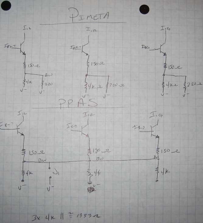
Bandwith - Quicksilver is correct, the bandwith is increased absent any resistor on jumper =p for the case where J1 is left open, its equivalent to having a 2k resistor on the pimeta. the bandwith there is *decent* and should allow high speed opamps to run without problem. If one really wanted to save up on battery, they could cut the bandwith traces.. but then why are you building a PPAS?
biggrin.gif


Basically the formula for determining the parallel resistor value is (1/2+1/R)^-1 which gives the equivalent resistor value in the pimeta.

Ozshadow - those opamp you said will work on the LR channel in closed loop mode, but dont try em on ground. those are opamps, not buffers (key difference). High output buffers that I know of are LMH6321, some current feedback types from National, HA3-5002,BUF634. you can also use high current opamps like OPA551.
 
Jul 6, 2006 at 10:58 PM Post #54 of 254
Got smd version of the 2107 coming, and already have my railsplitters. I do not yet know which buffer I'll use, but I am kinda worried about it being TOO smooth behind a buf634, but my next task is finding some of those.

I'm doing both a 2107/227 combo and a 8610/8620 - probably both behind buf634's
 
Jul 7, 2006 at 3:23 PM Post #55 of 254
Update on 6172s.. Reverse the reccomendation on them.. found one one problem, they start to get unstable as the battery voltages drop.. Ran them for one night and offset went from a managable 20 mV -> 1 V
redface.gif
Since I've not isolated the problem, i'll put the opamp under nonworking

The AD8066 config is working fine however.

But this is as far as I can go since I ran out of batteries.. I'll get some more tomorrow.
 
Jul 7, 2006 at 5:10 PM Post #56 of 254
My buffers are here!
biggrin.gif
biggrin.gif
biggrin.gif


I'm going to put them in and then I'll be able to give an initial impression of AD8610/20 and LMH6321.


Edit1: CRAP. Maybe it was just hooking up the wires, but I'm not getting left channel anymore. Right channel sounds REALLY nice, though.


Edit2: YES!!!! Works.
 
Jul 8, 2006 at 4:03 AM Post #58 of 254
Retraction of previous comments.. the 6172 seems okay the 6171 however is unstable under most configurations.. it just seems that the 6171 / 6172 combo is the worst.. it seems to thorw a large amount of offset..

The 6171 / AD8066 throws nearly 150 mV of offset, unacceptable (to me) and a large amount of heat in the ground opamp (also unacceptable)

The OPA132 / AD8066 combo is working very nicely so far.. I'll post how it goes.

First 10 minutes impression - What the heck?! this thing is ridiculous in the bass department.. like completely over the top.. I checked my equalizer.. I'm sure the bass will become more tame as I listen to it (psychoacoustic burn-in) but this lays the smackdown on my PPA v2 in terms of bass. it is a little bit lacking in the mids though.. Will post more impressions =p.

Hmm. Perhaps that was a mistaken impression. To be more specific, the OPA132 / AD8066 combo seems very source dependent.. the iHP-120 line out sounds far less bassy compared to the M-Audio transit output (well. I wasn't expecting *that* much out of the transit) more balanced and less missing mids. Or maybe I'm just getting used to the sound.
 
Jul 8, 2006 at 8:13 PM Post #60 of 254
Quote:

Originally Posted by quicksilver96
ATAT, steve - how much total current are your amps pulling? Are you running class A?

steve - what opamps are you running? Scanned the thread quick but I might have missed it.


AD8620/AD8610, LMH6321 in all 3 buffer positions. No class A or bandwidth resistor. I measured about 41mA at full volume into ~100ohm load (ER4P+75ohm adaptor).
 

Users who are viewing this thread

Back
Top