OPA627 + BUF634 prototype
May 17, 2002 at 10:13 AM Thread Starter Post #1 of 14

gavinbirss

Head-Fier
Joined
Oct 19, 2001
Posts
83
Likes
11
Hello,

Since seeing both Tangent and Tophu great attempts I felt the need to share my first
design / prototype and will only accept positive critizim.
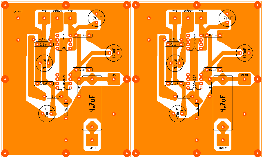
627634p.jpg


!!! Please note that this image is not actual size. !!!

First glance may reveal that I like thick tracks and lots of ground. My motivation for this
is since you are paying for a full board of copper you may just as well use it instead of
wasting it with the etchant.

Also that I have included two inputs. One that is capped and the other witch is not.

The only phones I used on the circuit are the AKG K 501's and a pair of 32 ohms test
phones. Only at levels you would not put the 32 ohm headphones on your head, the single
BUF634P per channel heats up slightly. (with a 8 ohm pc speaker it does heat up more).

Tophu and others will most likely agree that this circuit is sufficient for the AKG K 501.

During my time with this prototype I discoverd that more ( > +-12,15) DC volts make the
OPA627 and BUF634 come alive. My only concern is that I prever using batteries wich
limits you to moderate supply levels. I use two 12 V 7 Ah lead acid batteries in series
that is split to +12 and -12. (26 V in total on full charge). Later I have used +-15V
from a regulated wall wart. This I then sent into a resistor devidor because the output
of the two regulators did not match.

My other concern is with the level of the signal being amplified. The higher the supply is,
the lower the volume setting to produce the same level on the phones. i.e that you are
amplifying a more attentuated signal the higher the supply voltage. Almost like comparing
a moving coil cartridge to a moving magnet cartridge. (the level difference).

I plan to investigate further into better power supplies(+-15V), biasing the opamp into
Class A and using two BUF634T in parallel and also a preamp / headamp design.

Here is another board that I am going to try.
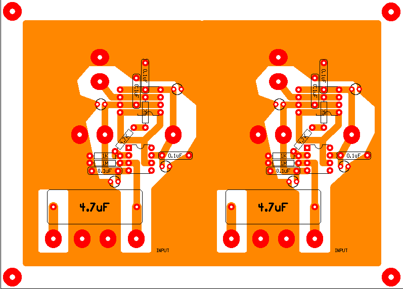
6272634t.jpg


Here I have to BUF634T's in parallel and I would most likely use
them in LOW bandwith mode or solder a wire from the BW pin to
the back side of the package. (which is electrically connected to
V-).

!!! Please note that this image is not actual size. !!!

I have tried the OPA637 and AD797 on this circuit and was unsucsesfull to say the least.
They both produced noise and seemed to be very sensative to the volume pot. Witch is a
cheap dual 50K pot of a precsion lab instrument.

Gavin
 
May 17, 2002 at 4:23 PM Post #2 of 14
Quote:

My other concern is with the level of the signal being amplified. The higher the supply is,
the lower the volume setting to produce the same level on the phones. i.e that you are
amplifying a more attentuated signal the higher the supply voltage. Almost like comparing
a moving coil cartridge to a moving magnet cartridge. (the level difference).


Actually no, the gain is set strictly by the feedback loop and is irrespective of supply voltage.

Quote:

During my time with this prototype I discoverd that more ( > +-12,15) DC volts make the
OPA627 and BUF634 come alive. My only concern is that I prever using batteries wich
limits you to moderate supply levels. I use two 12 V 7 Ah lead acid batteries in series
that is split to +12 and -12. (26 V in total on full charge). Later I have used +-15V
from a regulated wall wart. This I then sent into a resistor devidor because the output
of the two regulators did not match.


If your regulated wall-wart has slightly different voltages on the V+ and V- rails, it's usually of no concern. They could actually be off by several volts and your circuit would still operate fine. It would just limit the voltage swing available on the lower supply. I'd say if you're getting 14v on one and 15v on the other, that is fairly normal and of little concern.

On your bypass capacitors; from the looks of it, those are poly caps of some kind, no? Ceramic .1uF caps actually work better than audio grade caps for bypassing.

Nice layout!
smily_headphones1.gif
 
May 17, 2002 at 4:34 PM Post #3 of 14
Oh, one more thing... you've got it set for an input impedance of 1M-ohm. This is extremely high and besides being prone to DC offset, will make the amp very succeptible to picking up noise. RF, hum, johnson noise, everything... I would suggest changing that resistor to 100K, and you will still have a low frequency cutoff in the low single digits.
 
May 20, 2002 at 7:27 AM Post #4 of 14
Thank You Phloodpants
wink.gif


"Oh, one more thing... you've got it set for an input impedance of 1M-ohm. This is extremely high and besides being prone to DC offset, will make the amp very succeptible to picking up noise. RF, hum, johnson noise, everything... "

This would most likely explain the noise problems I had with the
OPA637 and especially the AD797. I will most definitely lower the value of this resistor. Would it help then rather to use a 10K or 25K pot ?

"Actually no, the gain is set strictly by the feedback loop and is irrespective of supply voltage. "

I agree about the gain but my concern is with the level of the signal that is coming out from the slider on the pot. Does the loudness you get on your phones not depend on this and if the supply voltage is doubled your loudness increases ?
confused.gif


I may need more convincing ...
confused.gif


How does the OP275 and BUF634 work. Tell me more about your
circuit configuration and how it
smily_headphones1.gif


Gavin
 
May 20, 2002 at 3:31 PM Post #5 of 14
Quote:

agree about the gain but my concern is with the level of the signal that is coming out from the slider on the pot. Does the loudness you get on your phones not depend on this and if the supply voltage is doubled your loudness increases ?


Nope, the loudness coming from the phones has nothing to do with the voltage of the power supply. A higher voltage supply will allow you to do more volume without clipping or distortion, but it does not affect the gain structure in any way.

A 50K pot should be good, but you say it's from a precision lab instrument of some kind. If that's the case, it's probably a linear type pot, not audio taper. I'd recommend a 25K audio taper pot, maybe 50K. Lower values will be less succeptible to hum and noise pickup, but you don't want to overload your source either.

The OP275 works great with the BUF634! I am running the BUF in wideband mode and it is perfectly stable, quiet and neutral. Dunno about using it in low bandwidth mode, but considering the phase response, it should work fine.
 
May 29, 2002 at 8:31 AM Post #6 of 14
With Phloodpants help I made some changes to my second prototype.

Here are some of the lessons I learned :

* Ground the volume pot mechanically as well as to the input ground. By grounding it mechanically you eliminate noise when turning to minimum volume.

* Your supply does not equate to loudness. Your gain, input impedance and volume pot value determines your loudness.

* A 100K input resistor delivers better sonic results as a 1M input resistor. (with a 100K volume pot)

* A logarithmic volume pot (audio taper) should yield better results than a linear pot.
 
May 29, 2002 at 3:25 PM Post #7 of 14
Gavin,

An interesting layout you have there. Two things I'd change: First, 4.7uF for the input cap is way overkill. 1uF is all you'll ever need. Use the extra space for other things. Second, I'd try to cram both channels onto a single board. It looks possible... Since you've got BUF634s, another thing you should look into is a buffered power supply. This will allow you the freedom of using a single supply without having to worry about unbalanced supply voltages.

As for the rest of the stuff that's transpired in this thread so far:

Changing the supply voltage doesn't affect gain, it just gives the op-amp room to "swing". If there isn't enough swing room for your combination of op-amp, gain, input signal level and supply voltages, the op-amp will clip or distort.

On the 1M resistor -- that shouldn't be a problem. Phloodpants: You should email Walt Jung to tell him that the 10M input resistor he uses in his multiloop article is incorrect. Don asbestos underwear first. In all seriousness: I've used 1M input resistors and they work fine. More to the point, making the input resistor 100K when the pot is 100K is definitely wrong. The input resistor should be larger than your pot's total resistance by at least a factor of 2. 10x is a common multiplier, so 1M is perfectly reasonable for a 100K pot.

The noise problem you got with the OPA637 is probably oscillation; that's a notoriously touchy op-amp. You can tell that a chip is oscillating if the amplifier draws much more current than is reasonable. Another clue is that the op-amp chip will get hot after being noisy for 10 seconds or so. (Note: Some chips run a bit warm all the time -- I'm talking HOT.)

To fix oscillation, try fiddling with the value and type of your bypass capacitors. Bigger isn't always better, for bypassing. You can also try paralleling two different types of caps. An 0.01-0.1uF ceramic in parallel with a 2.2-10uF dipped tantalum is a popular combination. Another thing to try is to raise the gain; you're only using a gain of 5.7, which is right on the edge of stability with this chip. Try 10 or more. If you don't want that much overall gain, you can add an output resistor inside the feedback loop. Also, you can try lowering the supply voltage -- that sometimes fixes oscillation, though it isn't a good long-term solution.

As for the AD797, I don't know what might have been happening there, since I've never used that chip. It could be oscillation -- all the same fixes pertain.
 
May 30, 2002 at 11:27 PM Post #8 of 14
The AD-797 is also a Picky Opamp. It is inended for High gain circuits like Mag phono. it is claimed to be unity gain stable, however it's Like 80-100 MHz. Bandwidth makes this chip less than ideal for line level stages. This opamp also uses Bipolar transistors as its input rather than Fet's. This requires some way to equal out the Bias Current. IMHO use this chip for your Finest Mic. and Phono Preamps, Buffer it with like a BUF-634 add a CRD or other Active Current source to bias it into Class A, Maby add a pair of FET source followers on the Imputs to get the really low noise the 797 is able to obtain and you will have one of the finest mag. phono preamps available providing a Great power supply and Quality Passive components.
 
Jun 3, 2002 at 6:29 AM Post #9 of 14
Hello,

tangent :

Input cap :

Why would you say that a 4.7 uF is an overkill ? Do you not use a
4.7 uF in your Meta 42 yourself ?

Supply :

I am using a single supply but am air wiring it to each board.

Gain :
Check again my gain is 6.7 in the first prototype. I am using two resistors in series. i.e 3 in total to set the gain. I did this to elimiate the need for a link. I was thinking of putting a pot there for ajustable gain.

I am however concentrating more on the second prototype and want to look into biasing the opamp into Class A.

Thanks
Gavin


smily_headphones1.gif
 
Jun 3, 2002 at 6:56 AM Post #10 of 14
Gavin,

I use 0.47 or 1.0uF input caps in my META42, and that's with a 100K input resistor. (You'll see why the input resistor's value matters in a sec.)

The formula you need to know is 1/(2 * pi * R * C). This tells you the "corner frequency" of an RC filter, such as that made in your amp by the input cap and the 1M resistor to ground. For those values, you get 0.03 Hz. If you bring the cap value down by a factor of 10 to 0.47uF, the corner frequency is still 0.3 Hz. If you used a 100K input resistor, you would bring the corner frequency up by another power of 10, to 3 Hz. Still quite good.

The corner frequency is the point where the rolloff of the filter is -3dB. Above this point, the filter tapers off towards 0dB rolloff rather slowly, so you want the corner to be well below 20 Hz. You can get a plot of the frequency rolloff by using the Microcap 7 demo and doing an AC analysis. You should also look at the phase shift chart it will generate, since an RC filter also affects the phase of the sound going through it.

Interesting trick with the feedback loop resistors.
smily_headphones1.gif


Another trick you might want to try is paralleling the input resistor, which makes balancing the input offset currents easier. This doesn't matter with FET-input op-amps, but with bipolars like the AD797, it does indeed matter. The idea is this: let's call the two paralleled input resistors R1 and R2, and the feedback loop resistors R3 (-IN to GND) and R4 (-IN to OUT). If you set R1 equal to R3 and R2 equal to R4, the currents are automatically balanced. Without the paralleled input resistors, you have to set R1 equal to (R3 || R4), which restricts the set of R1 values you can use. Let's say you wanted a gain of around 10 and an input impedance of 1M. You just need to find two resistances such that (R1 || R2) = 1M and (R2 / R1 + 1) = 10. One set that comes close is 10M and 1.2M.
 
Jun 3, 2002 at 7:38 AM Post #11 of 14
Hello,

tangent :

What caught me out whas the size of your caps and that I am
confused.gif
what 475K is. I am using 4.7 uF that look similar. Sorry about that.

I did not consider the cap value after lowering the input resistor.

Thanks for the help. cool:

What are your DIY plans after the Meta 42

Would you consider a USB DAC ?

I am going to post a new thread, please read it.

Gavin:
 
Jun 3, 2002 at 8:09 AM Post #12 of 14
The reason the input caps have been given so much space on the META42 board is to allow use of {metalized} polypropylene. If you use film and foil polypropylene (i.e. not metalized) you can get up to about 0.47uF in that space. If you go up to metalized polypropylene, you can get about 1.0uF in there. You're probably using metalized polyester, which is yet more compact. Some people scorn polyester for signal path use, but I've noticed a lot of commercial amps using metalized poly-e, so....

"475K" sounds like a resistor size. Where do you see that?
 
Jun 3, 2002 at 8:19 AM Post #13 of 14
Hello,

tangent :

Sorry my mistake your populated Meta 42 V 0.9 input caps have the markings P474G. I was relying on what I though I saw. My photographic memory must be going.


confused.gif


What time is it there ?

It it 10:17 am here now in South Africa, as I type this post.

Gavin
 
Aug 5, 2019 at 1:53 AM Post #14 of 14
I plan to investigate further into better power supplies(+-15V), biasing the opamp into
Class A and using two BUF634T in parallel and also a preamp / headamp design.

Here is another board that I am going to try.

6272634t.jpg


Here I have to BUF634T's in parallel and I would most likely use
them in LOW bandwith mode or solder a wire from the BW pin to
the back side of the package. (which is electrically connected to
V-).

!!! Please note that this image is not actual size. !!!

I have tried the OPA637 and AD797 on this circuit and was unsucsesfull to say the least.
They both produced noise and seemed to be very sensative to the volume pot. Witch is a
cheap dual 50K pot of a precsion lab instrument.

Gavin

Very, very long times ago ..... have anyone build that with two BUF634T in parallel in BW mode and AD797 (with 30 and 47 pF caps too)?
 

Users who are viewing this thread

Back
Top