


jdkJake
1000+ Head-Fier
- Joined
- Mar 16, 2009
- Posts
- 1,298
- Likes
- 16
Sweet.
That must have been some good beer!
That must have been some good beer!
Its new home, breaking in some 701s.
People who know me don't believe me when I say I built it.
But then I explain the support network.
And they still don't believe me... as I said, They know me.

Originally Posted by jdkJake /img/forum/go_quote.gif
Giving up on her already, huh?
Well, sorry to hear that. I was hoping we could walk you though it and get it up and running. However, I understand, you have to be willing to do it, or what is the point.
Not sure who could fix it for you. I am in the middle of another project (actually two), so, I really cannot take it on right now. Maybe in a few weeks. I would love for you to hear what that great little amp is capable of.
BobSaysHi, where in Texas are you located?
Hey guys, I'm back. I'm done fiddling with my amp. I simply have no idea what to do and where to look. I need a professional.
Is there anyone I can send it to to figure out whats wrong with it? Or could my local electronics shop fix it?
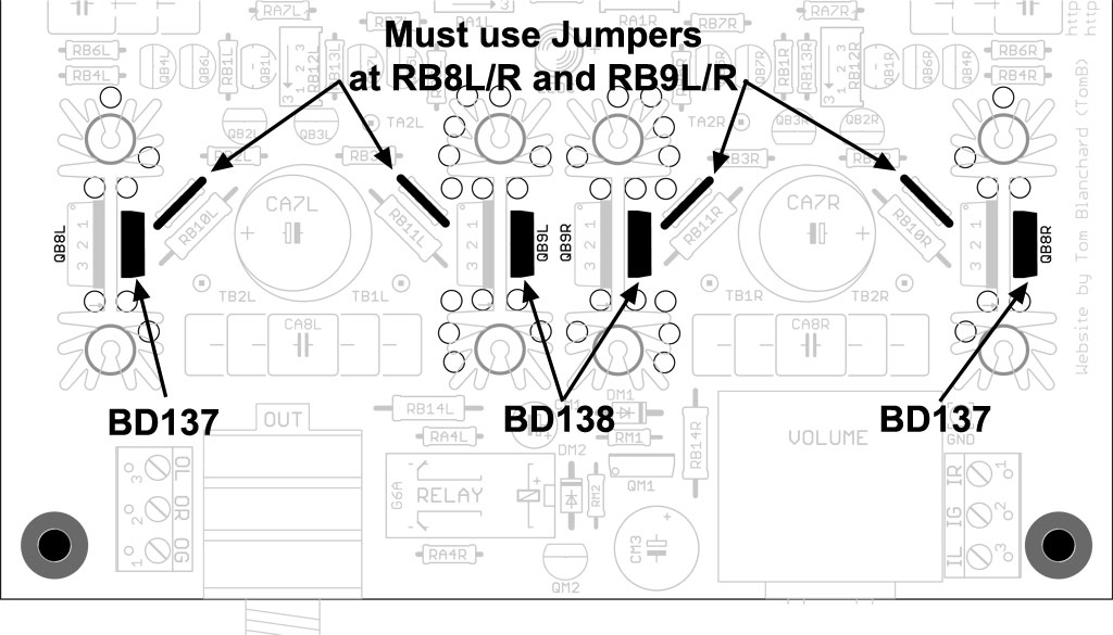
Just a preliminary look, BobSaysHi, but you've got several resistors mixed up in the primary tube circuit and CCS sections. That may be more than enough to cause the high-current drain. I'll keep studying it and let you know the specifics when I find them.
EDIT: It appears that the resistors are mixed up everywhere. Just as a gentle reminder for future reference for everyone, item #3 in the MiniMAX notes included with each kit states the following: "3. [size=11pt]... Despite what package the resistors are in, they may all be different. Make certain you either measure them or you understand the exponential notation of the rating."[/size]
[size=11pt]To make this even clearer, I'm editing the MiniMAX Notes to read as follows:[/size]
[size=11pt][size=medium]3. Please, please, please – install the V-D resistors (the little brown ones) so that the rating (the exponential numbers) is visible from the top of the board. Despite what package the resistors are in, they may all be different values. You must select the correct value resistor and match it up with the correct designation on the PCB. Make certain you either measure them or you understand the exponential notation of the rating. A 1K resistor will show “1001F.” A 100R resistor will show “1000F.” 1M is “1004.” The notation works by 100 multiplied by 10 to the power of the last number. Smaller resistances such as 10R are shown as “10R2” (actually 10.2 ohms) or something similar.[/size][/size]
[size=11pt] This is going to take me awhile, BobSaysHi ... [/size]


Oh, well that would explain why it wasn't working.
That is definitely what I did wrong. I didn't think to check the values when they were in the packages.
I didn't make it easy for you either, and I apologize for that.
I finished building my miniMAX last night, and have taken some measurements - for some reason the tube bias won't budge from around 23V no matter how much I turn the trimms.
The power supply is biased to 27V, both DB are sitting at around 90mV. I'm using the 12FK6 tubes atm, I have some 12FM6s aswell which I haven't tried yet.
Cheers!


Yep the tubes get warm and light up. I think I'm about 25 turns or so, so I will try checking the trimmers tonight. Haven't tested the amp for sound yet either- I think it was on for a total of 30minutes, so not sure if the tubes are still breaking in (first time dealing with a tube amp)
Cheers Tom for quick reply!
