scootsit
1000+ Head-Fier
- Joined
- Oct 23, 2011
- Posts
- 1,166
- Likes
- 41
Quote:
Yes. Tomb may want to chime in further.
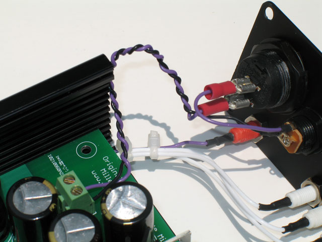
Asked tomb this same question by email, but thought I would post it here to in case it helps others or others can offer some advice.
Does the following wiring diagram look correct for the MOSFET-MAX power socket to SPST switch and PCB with fuse?
Yes. Tomb may want to chime in further.