odoe
100+ Head-Fier
- Joined
- Feb 21, 2007
- Posts
- 149
- Likes
- 12
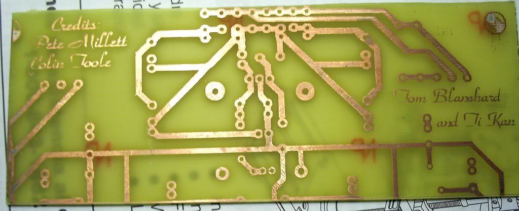
I have a proto board, the last version before the final as far as I know. Is there anything I should take into consideration when building it that's different from the final, aside from the lack of fuse
 ?
?