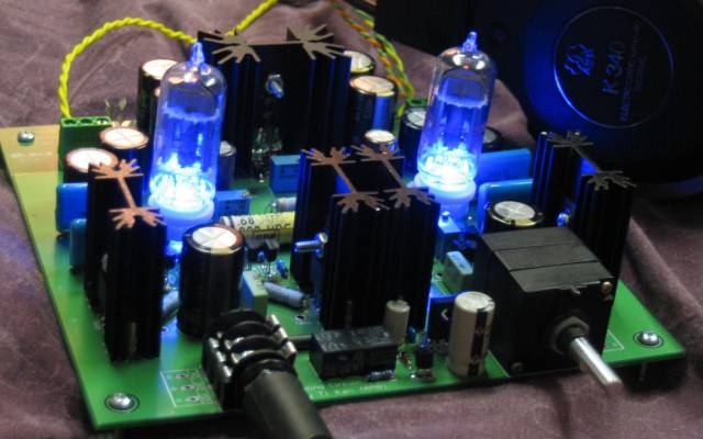
New Millett Hybrid Maxed Amp
Sep 18, 2007 at 8:40 AM Post #1,606 of 6,727
Quote:

Originally Posted by eddiewalker /img/forum/go_quote.gif
It was a close call after I got everything set up and biased, then couldn't get any sound output. Luckily all it took to make my new Max live was to reorient one of the diodes in the muting circuit.

Thanks to everyone involved. I'm enjoying this thing so much I'm going to have a hard time turning it off to figure out casing.


Another MAX lives! Congrats!
biggrin.gif
biggrin.gif
biggrin.gif

I know, it is hard to turn it off, the sound is beautiful.
 
Sep 18, 2007 at 9:34 AM Post #1,607 of 6,727
Quote:

Originally Posted by amphead /img/forum/go_quote.gif
My guess, is that biasing the DBs at a lower voltage produces more boom with less clarity, maybe more harmonic distortion. The available voltage swing would be less, as TzeYang says about the headroom. This results in clipping of the signal if driven harder, with the extra current pumping the headphones drivers. Usually not what you would want. Thus biasing the DBs higher, resulting in less current flow, but without harmonic distortion induced by clipping of the signal? Thoughts? :wink:


I'm nor sure I view things so similarly.. a transistor is kind of like a 'variable switch', or a dimmer.. it is a junction between 2 circuits, one usually lower current/voltage, and one higher. lets stick to current.. its pretty much the same with voltage though. anyway, by changing the current in the low current circuit, you're controlling the current flow in the high current circit in an almost analogous way. Now, the 'high current' circuit has its own limitations, and so does the transistor.. resulting in a 'saturation current', being the maximum current that can flow through it. so lets say it simply 'doubles' the current, ie, by allowing a small current in circuit a, it allows double the current to flow in circuit B. so(all numbers as examples alone), 0.5amp-> 1amp, 1amp->2amp... but lets say the saturation current is 3amps, so 1.2->2.4, 1.5->3, 1.6->3, 2->3 you get what I mean(clipping).. the thing is, its not a linear device, so it cant just double. invision a parabolic climb that straightens out somewhere for a bit then suddently becomes flat. kind of like:
0->0
0.1>0.05
0.2>0.2
0.3>0.4
0.4>0.7
0.5>1 (here its double, lets say it has becomes linear here...)
0.6>1.2 ....1>2.. 1.5>3 (now, saturation) 1.6>3 ... which is, basically, clipping.

so, the way I see it is that you can get larger current swings if you oscillate between (0..1.5)->(0..3) but it wont be linear, so a sin wave would look kind of funny. but if your oscillations would be between say (0.9...1.1)->(1.8->2.2) you would have an almost identical sin wave of double the current flow.. thing is, there is always current flowing (dc), but thats another paragraph, and what capacitors are for
biggrin.gif
but basically, unbiased.. the current swing can be higher, the headroom that I think he meant was the margin of linearity.. like, if its linear between (input of) 0.5 and 1.5, you can oscillate around 1amp(bias current) with a headroom of half an amp before you either start clipping or dropping out of class A linearity.....
anyway, I havent actually studied this stuff yet, so I'm likely to think differently in a year from now(ask me then
tongue.gif
) and I may be wrong/innacurate/whatevere.. or just making a mess with numbers.. I think google will get you further than I did
biggrin.gif
 
Sep 18, 2007 at 11:10 AM Post #1,608 of 6,727
Voltage is constant throughout the DB, regardless of current. The voltage is set by the PS. The signal voltage is set by the tube. That's called gain. The bias plus or minus the supply voltage is the amount of voltage/gain swing possible by the tube, minus a bunch of parts inbetween - most important the impedance of the headphone.

Amb made the following measurements on the original revMH Millett (without DB's):

* Maximum output voltage
(prior to onset of clipping, 12AE6A tubes, 27VDC supply, 13.5V bias)
5.85Vrms (16.5Vp-p) into 330Ω
2.85Vrms (8.06Vp-p) into 33Ω


This sort of gives you the idea. Signal voltage is set by the PS, tube bias, and the headphone impedance.

The real value the DB's Class A bias provides is how much current, therefore, power - since voltage is set by gain in the tube stage - the output stage is prepared to supply without transistor switching. That's what's meant by "remaining in Class A" with a heavy load. A very inefficient headphone may draw instantaneous current that exceeds the bias setting of the buffer. When that happens, the capacitors supply the instantaneous current and the transistors add switching noise when they respond to the greater current.

If the signal continues at that peak, the capacitors may deplete. Then voltage will also drop and clipping will start. All of this happens in the blink of an eye, of course.

A good example is if you've ever had experience with a variable flash on a camera. Flash at full power and you may only get one or two flashes before the batteries are called on to re-charge the capacitor. At a small flash power setting (as in more efficient headphone to the amplifier), you can get many more flashes before it has to stop to re-charge. However, get a professional flash with a special power pack, and you may be able to fire off dozens of full power flashes without any delay.

A deep Class A bias amplifier does the same thing for your headphones: fires off continuous, full-power "flashes" with no switching noise or clipping.

EDIT: I think what ruZZ.il explains is correct, too - but this is the way I understand it. I've probably said some things that are not technically accurate, but hope that it helps, anyway ...
 
Sep 18, 2007 at 6:11 PM Post #1,609 of 6,727
Quote:

Originally Posted by ericj /img/forum/go_quote.gif
Correcting those three mistakes cleared up my issues. Thanks for all the help!

Now i just have to enclose it. i'd been thinking of doing something creative and original, but now I'm thinking that that's overrated. 'cause i have no good ideas.

img_1193-crop-shrink.jpg


LOOKS awesome, don't suppose you have a picture from above, im trying to figure out if i can get some obligato 0.22uf's in there for CA8's and CA9's.

Also can someone explain about the corner frequency. Ive read it, and with the caps im going to be using (BG NX 680uf/35v) at CA7's will give a fequency of 7.31hz, not the recommended 2hz. How do i choose an output coupling cap as im considering the 630v 0.22uf obligatos ????? o and btw im using grado's.
 
Sep 18, 2007 at 6:14 PM Post #1,610 of 6,727
Quote:

Originally Posted by adfinni /img/forum/go_quote.gif
Also can someone explain about the corner frequency. Ive read it, and with the caps im going to be using (BG NX 680uf/35v) at CA7's will give a fequency of 7.31hz, not the recommended 2hz. How do i choose an output coupling cap as im considering the 630v 0.22uf obligatos ????? o and btw im using grado's.


I'm going to go out on a limb and say that not only can you probably not hear 7Hz but your headphones probably roll off at a far higher frequency so I wouldn't worry about that in the least. It's all well and good for some folks to take this design to the extreme with their choice of caps and whatnot but I think we've gone well past 11 when we start talking about a corner freq. of 7Hz being an unacceptable compromise.
confused.gif
 
Sep 18, 2007 at 6:37 PM Post #1,611 of 6,727
what nate said.
but anyway.. hm.. grados?
looks like you calculated it right. 1/(2*pi*r*c) while r=your cans. you can add an x ohm resistor if you like, so then its 1/(2*pi*(Rcans+Rres)*c). if you'd liek to, get some kiwames or other good resistors, and experiement.. you may get a lower corner frequency, but other side effects you dislike more. so, do your own balancing act
smily_headphones1.gif
 
Sep 18, 2007 at 6:46 PM Post #1,612 of 6,727
Adfinni - YGPM.

What these other guys said x10. To bypass if you're using BG's:

1. Nothing.
2. Vitamin Q's if you can get them to fit (not easy)
3. Buy the 0.47uF, 50V NX HiQ Black Gates and connect them in reverse polarity (Super E) as bypasses. These are only $2.50 ea where BG's are sold.

I believe #3 is how Nate did his old Millett, and at least one other has done the MAX this way. If it turns out the Super E is not as good as "nothing", at least you've only spent $10, and you can turn around and put them on a couple of Alien DACs.
wink.gif


P.S. Stay away from the Obligato's. The MAX's response and transients are way too quick for those things and they're huge, anyway. One other user (Zare?) tried Obligatto's and quickly changed to Hovlands. Hovlands are very expensive btw, and pretty large, too. Their claim to fame is very neutral, flat with extended to harsh highs. I'm not recommending them, just saying it's an example that the MAX doesn't necessarily do that well with the generally accepted sweet, syrupy old-style film tube cap. As Dsavitsk noted a ways back, Vitamin Q's are an exception, being surprisingly uncolored with extended, somewhat unfiltered highs.
 
Sep 18, 2007 at 7:03 PM Post #1,613 of 6,727
Thanks for all those reply boys, it's horrific trying to choose the correct cap combinations.

1.) im leading towards bypassing the NX's with some little 0.47uf NX HI-Q's, which i actually use in my old millett to bypass some BG standards. But if using these is not as good as nothing then it seems quite pointless.

2.) Im considering saving money on caps and going for 1000uF nichicon KZ's all round (even the PSU section) then using some 0.22uf hovlands in CA8's and 9's. But as you say they have extended highs and my grado's certainly don't need any more.

3.) FOund some 0.22uf vitamin Q's for sale here in england so am tempted to get 4 of them, but wouldn't know whether they would pair better with the KZ's or NX's...

O and obviously i have the 2SC3422 / 2SA1359 combo so it should be nice and bassy.

Lol isn't this fun
biggrin.gif
 
Sep 18, 2007 at 8:05 PM Post #1,614 of 6,727
There's almost no cap, nohow, better than a Panasonic FM out of the signal path. So, don't waste your money on boutiques in those positions. Better to buy as much capacitance as possible, within reason. I have 1800uf, 35V Panasonic FM's in one MAX, and 1200uf, 35V FM's in the other. The 1800uF's are the same size and height as the 1000uF, 50V FM's in the PS, so it looks "symmetrical."

Also, I didn't say that NO bypasses would be better than the 0.47uF BG's. I believe it's a matter of expense. From what we're learning, you have to put a very high quality film cap in there or it detracts from the quality of the BG's in the first place. However, I don't know first hand. Again, Dsavitsk is the master when it comes to this and is the only one to have done testing of any import. He said awhile back much the same - given a choice, he would always bypass the BG's, but if it came to a cheap bypass vs. no bypass, then no bypass.

I'm sorry that a lot of this is guesswork. I've got several orders pending, but it will be awhile before I have some test cases built. Honestly, it's hard to beat the ES's and the Wima's.
 
Sep 18, 2007 at 10:25 PM Post #1,615 of 6,727
Quote:

Originally Posted by adfinni /img/forum/go_quote.gif
....
3.) FOund some 0.22uf vitamin Q's for sale here in england so am tempted to get 4 of them...


how much are they there? there are a few on e-bay for pretty cheap.. just that you have to get a whole bunch. I'd be willing to share some with someone or 2..
 
Sep 18, 2007 at 10:40 PM Post #1,616 of 6,727
Quote:

Originally Posted by ruZZ.il /img/forum/go_quote.gif
how much are they there? there are a few on e-bay for pretty cheap.. just that you have to get a whole bunch. I'd be willing to share some with someone or 2..


They are £8.95 each for the new ones 0.22uf 400v (have fancy chrome and black outer skin), or £5 for the USA made ones that look like NOS. The NOS ones have a single nut fixing at the end but no leads ???
 
Sep 18, 2007 at 10:59 PM Post #1,617 of 6,727
Vitamin Q's on e-bay:

http://cgi.ebay.com/capacitor-0-22mf...QQcmdZViewItem
http://cgi.ebay.com/Capacitor-0-27mf...QQcmdZViewItem
http://cgi.ebay.com/Capacitor-0-18mf...QQcmdZViewItem
http://cgi.ebay.com/Capacitor-0-15mf...QQcmdZViewItem
http://cgi.ebay.com/Capacitor-0-47mf...QQcmdZViewItem

These are all from "LA Surplus Electronics Co.", and I can personally vouch for their good service, having ordered from them twice with excellent service. Those listed above are genuine "Vitamin Q" and stamped as such by Sprague. However, they're pretty big. There are others that are smaller that are "Vitamin Q - like" but not having tried any of these yet, I can't say for sure. MrMajestic2 and FallenAngel have some, but I don't know if they've tried them yet, either.

You will note that Colin prepared the board in the front specifically for these type of capacitors. The CA8 positions have a little more room, but the CA9 positions are more cramped. So, the pseudo test point was included in the CA9 positions. The Vitamin Q's are bead-soldered at the terminals coming out of the cans. The beads make a perfect fit in those holes when you tombstone one of them.
 
Sep 18, 2007 at 11:14 PM Post #1,618 of 6,727
http://cgi.ebay.co.uk/22UF-400V-DC-S...QQcmdZViewItem

^^^ THat's the confusing one.

Cheers for that tom, il pick up some like in the link above, then put them in once ive run in the millett. WIll start with just the BG NX's in C7 and C2, then burn them in and sub in the vit Q's to compare.
 
Sep 18, 2007 at 11:57 PM Post #1,619 of 6,727
Quote:

Originally Posted by adfinni /img/forum/go_quote.gif
http://cgi.ebay.co.uk/22UF-400V-DC-S...QQcmdZViewItem

^^^ THat's the confusing one.

Cheers for that tom, il pick up some like in the link above, then put them in once ive run in the millett. WIll start with just the BG NX's in C7 and C2, then burn them in and sub in the vit Q's to compare.


Yeah, most of those with the threads and the nut are pretty big - like maybe 2" long and 3/4" in diameter. They're not showing it in the pic in your link, but those usually have a lead on the other end, too. The ones I ordered from those links might be too big, too - I got some 0.47uf's that probably don't have in prayer of fitting and then the 0.22uf's are just as long but only about 1/4" in diameter. So, I might have a chance with those if I get creative.

So, watch those sizes and compare with what you've got room for on the board. If you're in the bottom slot of the Hammond case and going for 1-1/2" sinks, you can probably fit most of those by standing them up. That might be one way to do it.
 
Sep 19, 2007 at 1:45 AM Post #1,620 of 6,727
I have been trying out the other tubes.

I was surprised the 12FM6 would "have less decay" as if it's cut off(I'm not sure if I used the term correctly but it's that echoey trail) but, the FK6 seems to have that right amount (for me). I thought it would be proportional to the gain value of each tube. (Kind of like the next in line will be less and so on...) FK6 seem to be the least brassy (that certain jazzy timbre when the sax plays). I am not sure if I can even say it's the coolest sounding of the 3 (if the expression of warm is given to the sound of the tubes) but somehow it also sounds more precise and detailed.

By now you probably think I'm the most confused person here.
redface.gif


I have been taking measurements for tube bias since I am changing tubes and here is what I noticed.

As I adjust the vol knob up on the 12AE6 the voltage across the test points goes up but, with the other two, the voltage remains the same no matter how I adjust the volume. What is different between the 12AE6 and the other 2 type of tubes?
 

Users who are viewing this thread

Back
Top