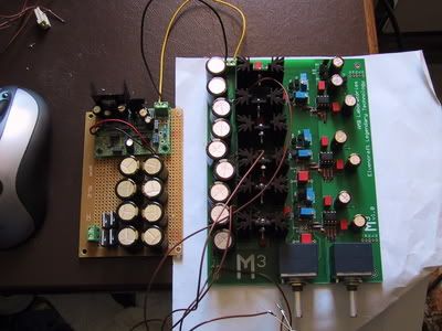
My M3 (or Jazper's M3 Monster)
Jun 17, 2005 at 5:47 AM Post #31 of 73
Lesson 2: always check the browndog adapter you're soldering to :S

after receiving some browndog adapters from a headfi member that were unmarked I soldered a pair of smt opa 637's to them. little did I realise that the adaptors are converters for use with single opamp chips to convert to dual, after trying desperately to desolder one of them after realising this fact, I've successfully killed a 637 (OUCH $$$) so.. while I do have one more 637 spare it still means I'm going to be a chip short (unless by some miracle I desolder the other) and it's going to take a lot longer before I'll have this going at this rate :S

:S

anyone wana swap a browndog 2x with 1x 637 soldered to it for a dip8 version of the chip?

update: pondering biting the bullet and buying an 8610, considering I have 2 kicking around..
 
Jun 17, 2005 at 12:17 PM Post #33 of 73
I don't believe it.. I managed to desolder the other one.. *shrugs* guess I was just too rough with the first. We live and learn
 
Jun 17, 2005 at 3:04 PM Post #34 of 73
Well good news on the case, my sister's boyfriend works as a toolmaker/turner/fitter for a racing team and has offered to build me a case from sheet aluminum, so I guess I will actually get a custom case
smily_headphones1.gif


smily_headphones1.gif
 
Jun 20, 2005 at 11:29 AM Post #35 of 73
well, a few more hiccups with the build,

first that I didn't order enough caps for C2/C6 (so I had to order them locally - and it cost a bit). However I got something better (WIMA, which weren't in stock at mouser)

Second the 35v/330uF SiLMICS are friggin huge, so much so that they've taken some serious bending to fit the board, so instead or a nice neat row of caps, they're a bit skewed in places.

Thirdly I tried welding:)P) the surface mount chips to chip sockets, but failed miserably after burning my hands many a time, so browndogs are on order. ETA when tangent sends them *shrugs*
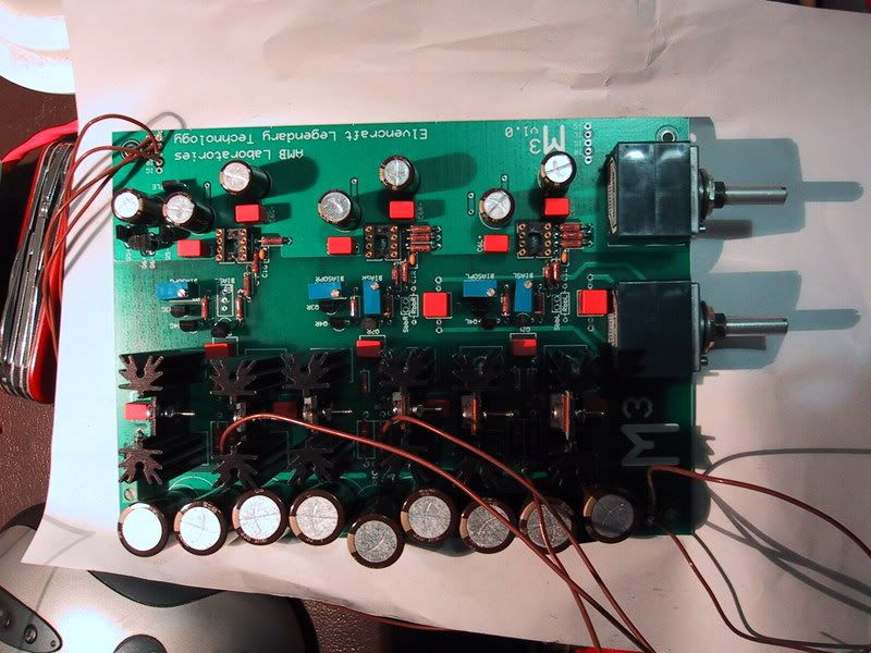
my digikey order still hasn't made it through the mail yet.. so I can't complete the power supply board, but the amp board should be complete tomorrow or the day after. I'd be able to test if it weren't for the opamps...

anyhow.. just keeping you all posted..

Jaz
 
Jun 20, 2005 at 10:14 PM Post #36 of 73
I'm having trouble with the JSR03, the parts are just too cramped together so it's very difficult to fit them in the board, the RN60D vishay resistors don't fit normally so I'm tombstoning and the polyprop caps are a real pain (some will HAVE to be polyester). overall it's very very fiddly so far.. so we'll see how I go. I'll persist but it ain't going to look pretty.
 
Jun 21, 2005 at 9:42 AM Post #37 of 73
One way to find out if it's worth the trouble with audiophilic parts is to build the regulator with "original" parts first. If you then are satisfied you know from where you are going when you start tweaking.

At this very moment you don't know if the regulator will work proberly at all. Remember that this regulator is a wibeband device so it requires some consideration when it comes to choices of parts.

The whole purpose of a super regulator is to let the active parts do the main task in forming a very low impedance and a very low noise voltage source.
 
Jun 23, 2005 at 6:56 AM Post #38 of 73
well an update, be it small

IMG_0541.jpg


IMG_0538.jpg


Pictures of the build first - I am aware the caps are "wonky" but they don't fit neatly. (note they're 330uF 35v silmics)

Also I'm aware that one of the trimpots on the m3 is missing, during the whole desoldering exercise I broke one of the leads, another should be here tomorrow or monday

Opamps - I got some TL071s today, will be trying them when i've got the final pot. I have some AD8610s and some 637/627s but they're all SMD, so I'm waiting on browndogs

progress on the case has started, I've toyed with a few designs and it'll be worthwhile when its done.

The JSR 03 (the regulator) is outputting 17.95v exactly(when I'm feeding it 29v from psu mk1), so something needs to be fixed or changed in the design there, I've been using psu mk1 (the one I described earlier) for m3 testing up to this point.

Made some changes to JSR03 - (some components removed now)
 
Jun 23, 2005 at 9:56 AM Post #40 of 73
Quote:

Originally Posted by peranders
Remember that you will need 33 volts in at least if you want 28 volts out. You should have 5 volts more than you want out.


with 32.2v in (unregulated) the voltage is the same (8.27v)
 
Jun 25, 2005 at 3:53 AM Post #41 of 73
so close.. yet sooo far

IMG_0564.jpg


The m3 is drawing 309mA. Quiescent current ~130mA

The JSR seems to drop out of regulaton as soon as the load comes on it (or shortly after) and it hits about 24v .. give or take

still troubleshooting with P-A

you might also like to know that the big psu caps are 1000uF panasonic FM/50v and they're the same size as the SiLMIC IIs which are 330uF/35v
 
Jun 25, 2005 at 5:32 AM Post #43 of 73
Quote:

Originally Posted by peranders
You must also check your raw voltage. What do you have really? It must not go under 34 volts. When you have 26 volts out, what have you in?


will check after lunch, but I'm pretty sure it's 34.2v

I'm looking for only 28v out..
 
Jun 25, 2005 at 6:01 AM Post #44 of 73
Quote:

The default recommendation is a regulated 24V DC power supply, that could support 0.5A of continuous output current. Ripple and noise should be as low as possible, 1mVp-p would be the maximum tolerable.


From AMB's site.

Why do you have to have more? I see no reason for it when you have a 24 volt AC at disposal.
 
Jun 25, 2005 at 6:03 AM Post #45 of 73
Quote:

Originally Posted by peranders
From AMB's site.

Why do you have to have more? I see no reason for it when you have a 24 volt AC at disposal.


Voltage swing..

but .. when I tried the 30V ac/500mA transformer, the results were the same..

it looks to me like the problem is the JSR.
 

Users who are viewing this thread

Back
Top