M³ amplifier build discussions thread
Aug 25, 2005 at 10:05 AM Post #706 of 828
Quote:

Originally Posted by Nisbeth
Cutting the profile isn't going to work, as you can't get the case back together again. I can send you some pics to show you what you're up against
wink.gif
Replacing the top/bottom (which is steel) and/or the front/rear (which is aluminium) is easy though.
/U.


Yes, please, I want to see these. How can you know where to send the pics?

Many thanks for the knobs and remote volume hints also

All the best

Greg
 
Aug 25, 2005 at 10:08 AM Post #707 of 828
Quote:

Originally Posted by amb
If you're going to be doing that, then you might as well make your own custom enclosure.


Ok, but how? Assuming I order the six faces, with holes for screw attachment. On which base? I don't have a chassis. Is there a custom chassis society with aluminium plying and hole punching facility outhere where one can ask for one piece?

Any comment welcome on how to build its own custom enclosure... :wink:

Many thanks

Greg
 
Aug 25, 2005 at 10:39 AM Post #708 of 828
the place to go to get single custom panels is a local machining shop. yellow pages is your friend. in my experience the guys at my locals have been really cool and helpful. pretty cheap too.
 
Aug 25, 2005 at 11:06 AM Post #709 of 828
Quote:

Originally Posted by GregVDS
Ok, but how? Assuming I order the six faces, with holes for screw attachment. On which base? I don't have a chassis. Is there a custom chassis society with aluminium plying and hole punching facility outhere where one can ask for one piece?


For the top/bottom/side panels you don't really need Front Panel Express, since (I assume) you won't have any markings. Just get a local metal fabricator or machine shop to cut and form sheets of aluminum to size and then you could either prep and paint them, or have them treated in some way (anodize, etc). Then, just join all the pieces together with angle brackets and screws. For the small screw holes you could just drill them yourself.

You really don't need anything fancy to make an attractive case. My own M³ prototype lives in a home-made case. The base is formed from a piece of sheet aluminum, bent into a U-shape (see this picture, and then I added acrylic side walls, mounted to the aluminum base with aluminum angle brackets and screws. The front and rear panels, also acrylic, are then attached to the side walls with more bracketry. Finally, the top cover is a clear acrylic piece, which screws into the sidewalls. See this picture to see the finished product. More pics from various angles can be found in the gallery section of my M³ site. Instead of acrylic you could do something very similar with aluminum.
 
Aug 25, 2005 at 3:12 PM Post #710 of 828
ok,

Thanks AMB and Skyskraper.

I will try this way.

AMB, What shipping method does Elvencraft use to send orders through the website? When will I receive all the stuff?

I can't stand waiting to begin this :wink:

All the best

GregVDS

ps, where can I find reviews of the M³?
 
Aug 25, 2005 at 4:38 PM Post #711 of 828
Elvencraft ships nothing, as it is my domain name. Send amb private email to discuss shipping issues. Use the search function to find reviews on the M³ in these forums.
 
Aug 26, 2005 at 8:53 AM Post #712 of 828
Quote:

Originally Posted by morsel
Elvencraft ships nothing, as it is my domain name. Send amb private email to discuss shipping issues. Use the search function to find reviews on the M³ in these forums.


Ok, Do apologize me for the confusion, Morsel, I was thinking this was in my order reply email, hence this was shipped so.

Greg
 
Aug 26, 2005 at 11:02 PM Post #713 of 828
Quote:

Originally Posted by GregVDS
Yes, please, I want to see these.


See here:
dac1b.jpg

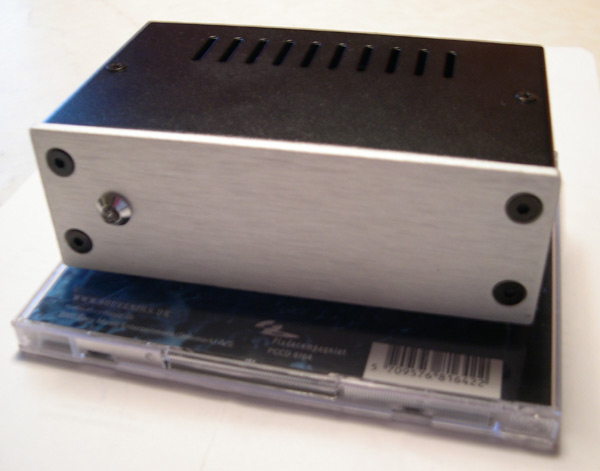
You can see how the front (3mm aluminium - rear panel is identical except black anodized) is fixed using countersunk M4-screws. You can replace the front and rear panels easily enough and/or use other screws if you like. You can also see the small countersunk M3-screw that holds the top (1.2 mm steel) in place (bottom is identical). You can replace these panels as well if you like and/or use different screws.

dac1c.jpg

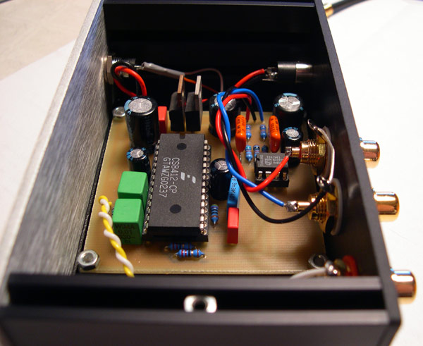
Now see how the assembly works. The top and bottom is attached to the M3-nut you can see (there's normally two nuts but this is a very small enclosure). This is a standard M3-nut which simply slides into a groove in the side profile. If you cut some of the profile away, you will not be able to fix the top and bottom anymore. The front and rear screws go into tapped holes in the end of the side panels. You could change the length of the sides if you wanted to, as that would only require you to shorten the profiles and then re-tap the holes in one end of the profile.

Hope this makes sense!


/U.
 
Aug 28, 2005 at 9:41 PM Post #714 of 828
Thanks Nisbeth for your explanations, I let down my idea on the galaxy, though I still think it is possible. I was planning in fact to lower down the height of a 8cm height galaxy box. If you look at it, I think the side panel (extruded ones) are made with two normal extruded piece, each 4cm height. If one cuts each to 3cm height, conserving the parts with the tapped holes for front and rear, I think it is still possible to reassemble the box.

But as AMB suggested me, it is maybe more meaningfull to build the enclosure from scratch, so, I choose this way: 6 panels from front panel express (too much money at the moment for me, but in a near future), assembled together by aluminium corner profiles. You just have to carefully plan wher to put holes and stuff like that. As soon as it is possible to show this, I will!

Roughly, I plan to build the M³ with internal psu, in a box 238mm width, 19mcm depth and 63mm height. I cannot go lower than this to and still conserving symetry in the front panel (neutrik, multiswitch for crossfeed, logo, bass boost and volume, each at 1,5 inch of distance to each other), and positioned also in the center vertically (need some clearance on the top of the 1.5 inch heatsinks). I could maybe diminish a little bit the depth, but I need to look if ther is still enough room for mains connector depth, STEP pcb, Linkwitz pcb, and neutrik and multiswitch in front.

I will post my design, to have comments about it.

Many thanks for the pictures and explanations again

All the best

Greg
 
Aug 29, 2005 at 1:23 PM Post #715 of 828
Great reading about the case. Please keep us posted on the development. I will soon have to figure out how to case my M³. Hopefully I can do the setup of the amp in a day or two, except for the bass boast that has to wait since I lack the appropriate capacitors. So, chances are I will be screaming for help soon if I don't get things working at first try...

The PSU is ready and tested, and all parts on the M³ board except the bass boast and MOSFETS are in place so far. Actually I still have to put on the connectors and possibly the power LED.
Perhaps I wait with the power LED until I have decided on what case to use.
 
Aug 31, 2005 at 5:07 AM Post #716 of 828
Just finished my M3 with a Hagerman Bugle phono board and STEPS incorporated together in the same case. Sort of an M3 integrated amp. All went very well during testing until I measured the DC offset. That's where things are really screwed up! Here's what I got: Left ch. = -1.4 mV: Right ch. = .6 mV: Ground ch. = 0.0 mV. If I flip the leads of my meter on the left channel, then it reads +1.4 mV. What gives? I assembled it very carefully, double checking everything, and followed AMB's setup exactly!!!!
 
Aug 31, 2005 at 5:36 AM Post #719 of 828
Switch the opamps around (left goes in right, right goes in left) and see if the DC-offset stays the same on the left channel.

Quote:

Here's what I got: Left ch. = -1.4 mV: Right ch. = .6 mV: Ground ch. = 0.0 mV. If I flip the leads of my meter on the left channel, then it reads +1.4 mV. What gives?


Nothing wrong with that behavior.
The + and - voltages should switch when you reverse the polarity of the meter.
wink.gif
 
Aug 31, 2005 at 8:46 AM Post #720 of 828
With regard to ordering silver solder (mentioned by GregVDS): This isn't a big deal one way or another, but silver solder is actually slightly less conductive than good old 60/40. In order to get the 1 per cent silver (which really doesn't melt that easily), they need to drop the tin content and increase the lead content to lower the melting point. And lead is not as good a conductor as tin... So in order to get a tiny amount of silver, you're diminishing the electrical quality of the solder in general.

The only place where you actually need silver solder is where you're soldering components (i.e. connectors) that have silver-plated contacts. Regular solder has a tendency to wick the silver plating off the contacts, and silver solder preserves it.

Aside from that application, "regular" solder is actually slightly better electrically, and is easier to work with, and a lot cheaper (though as I said the differences aren't huge).
 

Users who are viewing this thread

Back
Top