Little DOT MK III Mods??
Sep 14, 2009 at 10:23 PM Post #31 of 200
Quote:

Originally Posted by Pricklely Peete /img/forum/go_quote.gif
I bypassed the WIMA 3.3uf 50V MKP output coupling caps with a pair of NOS T-3 Russian 0.1uf 600V Teflon caps ....


According to this picture of the MKIII pcb, the WIMAs are 2.2 uF and not 3.3uF, right?
MK%20III%20Front.jpg
 
Sep 14, 2009 at 10:35 PM Post #32 of 200
On mine they were 3.3uf but I can't be sure what value they are for all the MK III's. The MK IV uses/or used to spec 2.2uf 630V Solens (whatever brand you have in yours now I forget).

Peete.
 
Sep 15, 2009 at 5:33 AM Post #33 of 200
Quote:

Originally Posted by Pricklely Peete /img/forum/go_quote.gif
On mine they were 3.3uf but I can't be sure what value they are for all the MK III's. The MK IV uses/or used to spec 2.2uf 630V Solens (whatever brand you have in yours now I forget).


The world famous 'Phenix HiFi'
k701smile.gif

2.2uf 250V (not 630V).
 
Sep 17, 2009 at 3:25 PM Post #34 of 200
Quote:

Originally Posted by Pricklely Peete /img/forum/go_quote.gif
I'd also pull the WIMA box caps and replace those with same value types of your fav brand (size is a limiting factor obviously) but I've never found the WIMA sound to be anything special other than the Black Box WIMAs that cost a fair pile of dough (but would be ideal in this spot).
Peete.


Peete, about the WIMA Black Box caps, are there different types? On a thread elsewhere on the web someone advised to get WIMA Black Box film and foil and not metallised!
The ones I've found are Metallized Polypropylene. Will they do?
WIMA audio Capacitor

-Sebastian
 
Sep 19, 2009 at 9:14 AM Post #35 of 200
Quote:

Originally Posted by Pricklely Peete /img/forum/go_quote.gif
The generic metal film resistors could be subbed with Vishay/Dale (matched pairs would be a good idea for the signal pathways).


Could you point out which resistors are in the signal path on the MKIV (or on the MKIII for that matter)?
I enclose a photo of my MKIV with two groups of resistors that I think are in the signal path (A & B). My marking of the A group shows both left and right channel whereas group B only shows one channel.

-Sebastian
 
Sep 25, 2009 at 3:05 AM Post #37 of 200
Quote:

Originally Posted by SebastianL /img/forum/go_quote.gif
Pricklely Peete,
what kind of wire did you use for the extension of capacitors you placed outside the box? Or what wire would you recommend?

Sebastian


I used some bog standard 20 awg OFC copper hook up wire I had left over from another project. If the MK III was easy to take apart I'd change it to the stuff I now have (in abundance), Mundorf Silver/Gold but 22 awg solid silver or 22 awg stranded high quality copper is more than good enough. Whatever you can lay hands on for a decent price should suffice. Keep in mind the amp is low cost so no crazy expensive wire is necessary.

Peete.
 
Sep 25, 2009 at 3:20 AM Post #38 of 200
Quote:

Originally Posted by SebastianL /img/forum/go_quote.gif
Could you point out which resistors are in the signal path on the MKIV (or on the MKIII for that matter)?
I enclose a photo of my MKIV with two groups of resistors that I think are in the signal path (A & B). My marking of the A group shows both left and right channel whereas group B only shows one channel.

-Sebastian


The resistors in the gain network (via the slider selectors) are I believe in the signal pathway. Order and then match pairs of 1% tolerance or better Vishay/Dale..Holcro or Caddock. Email David and ask for the other spots that should be considered and the Wattage ratings. I know the PSU resistors LD used to spec (just the Mk IV/IVSE) were barely adequate and caused quite a few MK IV's to fail but I believe Sword and David have addressed this issue. IMO though you can get very good quality power resistors (with tighter tolerances 1% vs 5%) for not a lot of money. Might as well right ? What value are the 2 yellow metal/poly film caps in the pic ? I'd also replace these (if they are Hovland then don;t bother...but I doubt they are).

Peete.
 
Sep 25, 2009 at 12:33 PM Post #39 of 200
Quote:

Originally Posted by Pricklely Peete /img/forum/go_quote.gif
The resistors in the gain network (via the slider selectors) are I believe in the signal pathway. Order and then match pairs of 1% tolerance or better Vishay/Dale..Holcro or Caddock. Email David and ask for the other spots that should be considered and the Wattage ratings. I know the PSU resistors LD used to spec (just the Mk IV/IVSE) were barely adequate and caused quite a few MK IV's to fail but I believe Sword and David have addressed this issue. IMO though you can get very good quality power resistors (with tighter tolerances 1% vs 5%) for not a lot of money. Might as well right ? What value are the 2 yellow metal/poly film caps in the pic ? I'd also replace these (if they are Hovland then don;t bother...but I doubt they are).

Peete.


I already mailed David about this and I'm waiting for a final reply (first off he replied about the risk voiding the warranty etc.)
The two yellow caps are german ERO 0,47µF +/- 10% 250V and I ordered some Russian K42Y-2 PIO caps to sub them.
As yet I have replaced the four WIMA caps with danish Jantzens and after some burn in, they did their job. The lacking of high treble is gone, which for me was a huge issue. The MKIV box doesn't leave much space, but I managed.
When I first got the MKIV I was quite dissapointed with the sound considering all the fuss and hype about this amp on this forum. Little 'tube' sound, lacking high treble, mushy bass and so on. Now things are looking better with my first mod.
As soon as the Russian K75-10s arrive I will try to swap the original noname (Phenix HiFi) caps and give it a listen. Eventually I will try to substitute these with Ampohms or mayyyybeeee Mundorfs.
 
Sep 26, 2009 at 1:43 PM Post #41 of 200
These are the resistors in the signal path on the MKIV according to David:
MKIV%20signal%20resistors.jpg


To quote David: "The only resistors that you should change are the ones in Group A, which are the gain resistors."
 
Sep 26, 2009 at 3:50 PM Post #42 of 200
"It's best to overengineer and choose the highest wattage you can find. The signal resistors in circle B will not really make much of a difference, but replacing the gain resistors in A may make a marginal improvement."

Quote David of Little Dot who's been very helpful as always
happy_face1.gif


-SebastianL
 
Oct 1, 2009 at 9:16 PM Post #43 of 200
Hello SebastianL,
Any news from the "war zone"?
smily_headphones1.gif
Probably I'm not the only one who is checking this thread every now and then to see the progress in your LD modification
smily_headphones1.gif

Best of luck!
sonda2008
 
Oct 1, 2009 at 9:39 PM Post #44 of 200
Quote:

Originally Posted by SebastianL /img/forum/go_quote.gif
"It's best to overengineer and choose the highest wattage you can find. The signal resistors in circle B will not really make much of a difference, but replacing the gain resistors in A may make a marginal improvement."

Quote David of Little Dot who's been very helpful as always
happy_face1.gif


-SebastianL


Get some Caddock or Holcro 1/2 W or 1W (tighter tolerance the better) matched pairs for the gain sections.There is no need to go above 1W with 1/2 W being ideal in this particular part of the circuit.
Partsconexxion offers matching services for a small fee...they have a great selection of high quality parts to choose from.You could ignore the gain pairs that you never use and just concentrate on the pairs that you do use or change them all. The difference in cost is only 10 or 15 bucks.

Every little bit helps even though David seems to think not a lot can be gained...I disagree..generic metal films in the signal path can do some SQ damage that can be repaired with high quality great sounding replacements. The K75-10's used in conjunction with the T3 Teflons is a fabulous combo...it's my personal fav but the caps are huge and present an installation dilema (as you know from my efforts). Fortunately it's a minor dilema easily solved
smily_headphones1.gif


The sub of the cheap Eros poly film for K series PIOs is a worthy upgrade. You've already noticed how pulling the WIMA's for something better can make a big diff. Personally I don't know why people like WIMA...I think they sound like crap (except the Black Box types which are PIO...
biggrin.gif
) in the signal pathways . Don't forget to bypass all the large filter caps with small value 250V or better PIOs.

Anyway good job thus far on the mods Sebastian ! I look forward to hearing how each step progresses and what you think of the results
smily_headphones1.gif


EDIT: The large resistors in the B section of the photo look to be 2W...I would go with no less than 3W in these spots, again get the pairs matched and the tightest tolerances you can find.

Peete.
 
Oct 5, 2009 at 7:29 AM Post #45 of 200
Quote:

Originally Posted by sonda2008 /img/forum/go_quote.gif
Hello SebastianL,
Any news from the "war zone"?
smily_headphones1.gif
Probably I'm not the only one who is checking this thread every now and then to see the progress in your LD modification
smily_headphones1.gif

Best of luck!
sonda2008


Hold on! I’m still in the progress of modifying my MKIV. But things are definitely going my way.

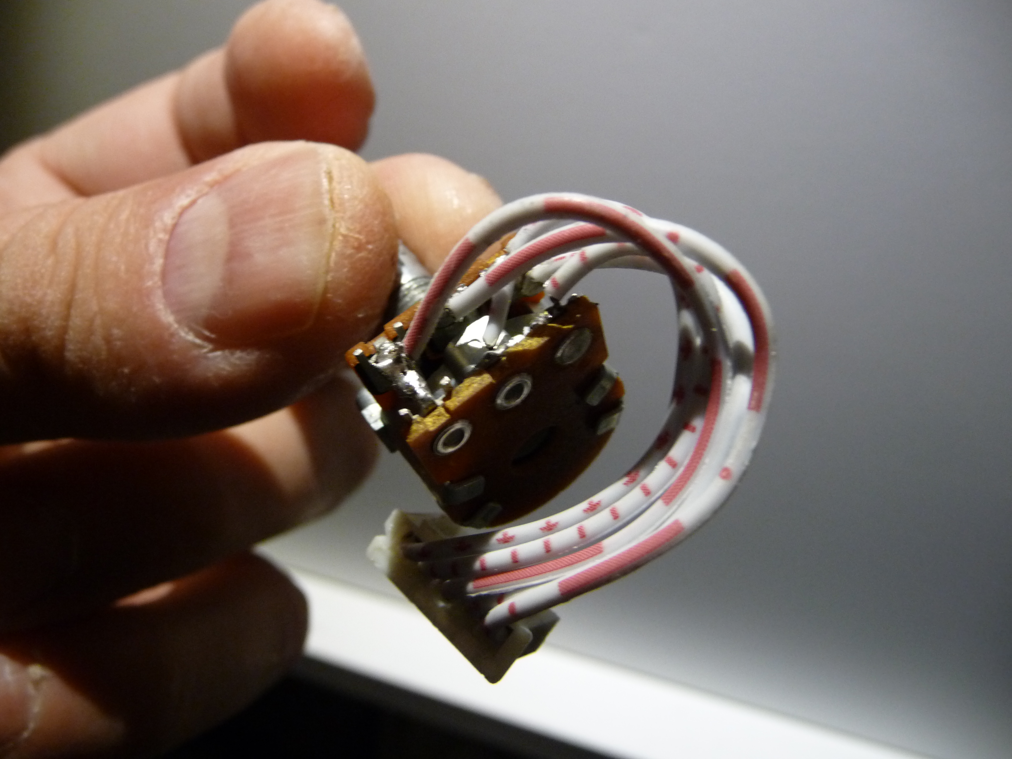
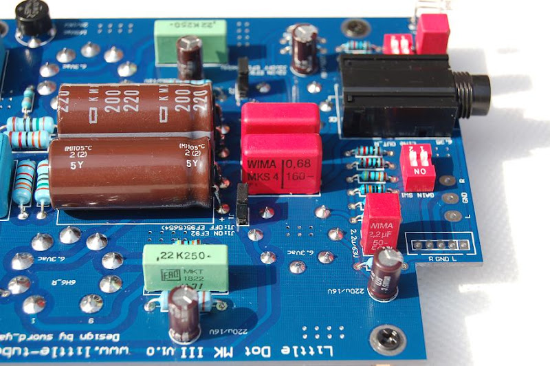
By now I have more or less followed the suggestions laid out by Pricklely Peete substituting the WIMA MKS4 caps with Jantzen Superior Z-caps. The Jantzens was my own choice though, since I’ve heard a lot of good reports about them. Furthermore they are a Danish product and I bought them in a store just down the road from where I work. Buying them was an easy task. However installing them wasn’t easy at all! There is very little space inside the LD box. Perhaps that’s why they call it LITTLE dot
wink_face.gif


Subbing the WIMAs with the Jantzens (the first mod I did) made a HUGE difference on the SQ. WOV! The annoying lack of treble (the biggest issue for me) was gone. Now, a lot of clear treble – maybe adding a tad too much emphasis on the high frequencies. But I was so content I was about to stop the modding process. However I had already bought or ordered a lot of other components. Thus, I went on tweaking.

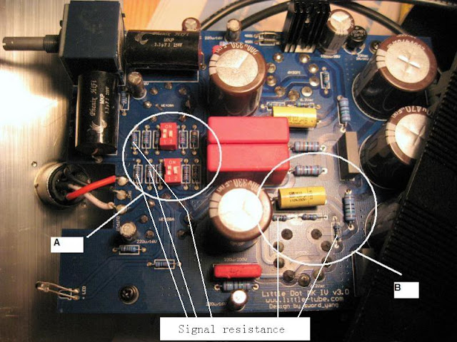
Next step was installing the Russian K42Y-2 .033µF 500V PIOs as coupling caps on the five big electrolytes on the back of the PCB. Also I subbed the two yellow ERO 0,47µF with Russian K42Y-2 0,47µF PIOs. Last step this time was exchanging the output wire w. some expensive AudioNote AN pure silver wire (solid core and very stiff – a bit difficult to work with, but the advantage is that it gets a strong grip on the front lid).
This (so far) last step brought it all back into balance. At this point once more I’m hesistating on continuing the mods because I am SO satisfied with the result: transparence, even balance throughtout the spectre, great stereo perspective, good depth, great dynamics. This is what I expect from a tube amp. I could easily live with this modded amp forever! (considering the money and time spent).

Once I’ve done all of the mods I will elaborate my statements and and draw a final conclusion. So far I’m very happy with the overall sound. Much more refined than the standard MKIV amp I received.
Note that I use Sennheiser HD650 with this amp which is very important to take into consideration when reading this report. The above mods might not suit other headphones at all. Just this weekend I tried a pair of HD800 with my modded MKIV and I preferred my own HD650+MKIV combo. The HD800 sounded much better with some other equipment (a HeadAmp GS-X).

Also to anybody who might want to mess with this amp: heed the warning from Pricklely Peete “the chassis the MK III is shoehorned into is a major PITA to pull the pcb out of and then get it all back in again. You need the patience of a Saint IMO to work on this amp.”!!!
He is so right!! Warning goes for the MKIV as well.

regards, Sebastian (a happy modder)
smily_headphones1.gif
 

Users who are viewing this thread

Back
Top