Koss E90 (driver unit in the ESP950 ESP95x package) modifications
Dec 15, 2020 at 2:01 AM Thread Starter Post #1 of 47

AudioCats

Headphoneus Supremus
Joined
Feb 25, 2007
Posts
3,726
Likes
264
Location
CO, USA
starting a thread for E90 related info


*** Post #5: front plate removal
*** Post #30: parts-list for a basic upgrade.


Disclaimer: info might not be complete/accurate; for casual reading / entertainment purpose only


opening the case requires peeling off the thin aluminum face decal, the decal deforms easily so don't attempt this unless you really want to get inside the case..... warming it up first (using a light bulb) helps.

IMG_0063.JPG


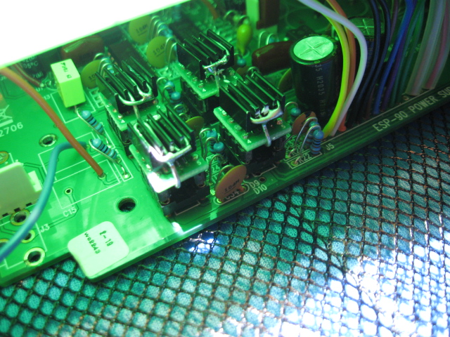
top board has 9 brown film caps, 0.022uf/630v (the one close to the face plate is probably for bias circuit); two opamps, MC33077; two opto isolators H11G1

IMG_0064.JPG


bottom board:
signal: from the RCA jacks, there are two 1uf input caps, then two TLC2082 opamp (u7/8, forms some kind of buffer) , then two MC33077 opamp (u5/6),

then one TLC2082 (u9), not sure if it is for audio signal or not.

power supply: U2=LM393, U3=TLC27M2CP, U10=TLC27M4CN, U4=74HC02N

** power input reservoir cap C33 is 2200uf/10v (this cap is always connected to the power input jack, whether the amp switch is on or not).
So it is, at least in theory, NOT OK TO USE voltage higher than 10v. However the Koss stock wallward outputs 13.3v no load and 11.2v idle, and C33 will see these voltages as long as the wallward is plugged in.....not sure why C33 survives. Maybe it is super grade stuff.

IMG_0076.JPG


update: observation, C33:
bought a spare E90, was intending to leave it fully stock but couldn't help myself.... opened it to take a look and found the C33 is popped in this one. It is a massdrop model so can't be that old. it still works fine. I guess it doesn't matter that much after all, might degrade the sound quality a little but likely not noticeable without direct comparison to a fresh E90.
IMG_0124.JPG
 
Last edited:
Dec 16, 2020 at 12:06 AM Post #2 of 47
Disclaimer: info might not be complete/accurate; for casual reading / entertainment purpose only


power supply board:
** the C33 is power input reservoir but just for the transistors (which drives the transformer).
** All logic IC's run on 5v, comes from U1 (LM2950, 5v). The front panel power switch controls the power that goes to U1.

+/- low voltage (to run opamps):
transformer coils-> D3/D4 --> C5/C7-->R9/R10 (47ohms) --> C6/C8 --> op-amps and the ribbon cable
(to user higher quality +/- power, remove R9/R10 and insert the voltages there).

+/- high voltage (about 600v)
transformer coils --> D2/D6 --> R13/R14 (1k) --> (C10+C11)/(C26+C27) --> ribbon
HV monitoring done by R6(5.1M) + R20(5.1M), R25(104k) --> top half of U9 (current buffer ) --> R12 (1k) --> U2


ribbon cable voltages, at various input power voltages:
** C33 changed to 40v to handle the higher input power voltage
** measurements done at the amp board, points : ("J1" silk screen) #14, 13, 12, 11, 10, 9, 8, 7, 6, 5, 4, 3, 2, 1 (#1 is square pad)
#14= HV+,
#12= HV-,
#10= to ISO2,
#9= to ISO1,
#6= LV-,
#5=GND,
#4=GND,
#3=LV+

with 9v input, #14=585v, #13= -598v, #10=9v, #9=9v, #6= -12v, #3=12v
with 12v input, #14=579v, #13= -598v, #10=12v, #9=12v, #6= -11v, #3=11v
with 14v input, #14=566v, #13= -597v, #10=14v, #9=14v, #6= -9v, #3=9v
with 16v input, #14=581v, #13= -597v, #10=16v, #9=16v, #6= -10v, #3=10v
 
Last edited:
Dec 19, 2020 at 2:17 AM Post #3 of 47
Audio signal path on the bottom board. Probably not 100% accurate but enough to give an idea of what is going on:

RCA input --> 1uf dc blocking cap (very small film cap) --> 1/2 LTE2082 as current buffer --> 1/2 MC33077 variable-gain stage (the volume pot adjusts the gain)
the signal then goes back to LTE2082 for current buffering, the output signal then goes to the ribbon cable; 1/2 MC33077 then invert this same signal and send to a different line in the ribbon cable.

E90 bottom audio signal path.jpg


The strange part is that the inverted and non-inverted version go thru different kinds of opamps. I suppose it would be better to have the same kind of chips for both signals.

*** key specs of stock opamps:
TLE2082:
-- JFET input,
-- 20nV input noise density (quite high)
-- 2.2mA current draw
-- 45V/us slew rate

MC33077:
-- 4.4nV input noise (average)
-- 3.5mA current draw
-- 11V/uS slew rate

*** some possible upgrade options:
AD8599 ($9 each)
-- 1.1nV input noise
-- 14v/uS slew rate
-- 2uS setting time
-- 5mA current draw
the sound signature is dark and rich.

AD8397 ($7 each)
-- 4.5nV input noise
-- 50V/uS
-- no setting time in spec sheet
-- suitable for driving capacitive loads, so maybe a good option for the top board.

LME49720 (LM4562) ($2.5 each)
-- 2,7nV input noise
-- +/-20v/uS slew rate
-- 1.2uS setting time
the sound signature is analytical (dry, cold, and detailed)

OPA627 (single opamp, $25 each; to make a dual-opamp will cost about $55)
-- 4.5nV input noise
-- 55V/uS slew rate
-- 500uS settling time
-- 7.5mA current draw (each; so will be 15mA for a dual-opamp module)

I will install IC sockets and try these out.

**** U9 (MC33077) is not directly in the audio signal path so no plan to upgrade it.

IMG_0077.JPG
 
Last edited:
Dec 19, 2020 at 3:21 AM Post #4 of 47
Possible capacitor upgrades:

*** bottom board signal path: C1/C15, stock caps value 1uf;
needs 2; max physical size allowed is maybe 1" OD x 1.5" length.
AudioCap Theta, 1uf/200v, 0.74"OD x 1.2"L, $20 each
AudioCap Theta, 2uf/200v, 0.93"OD x 1.2"L, $23 each
Multicap PPFXS is the same as Theta but with a more flat shape
Dynamic cap 1uf/425v, 0.7"ODx 1.55"L, $33 each

*** top board, signal capacitor upgrade options:
stock caps are 0.022uF/630v;
needs 8; to fit into the original enclosure, the max physical size is about 0.5" diameter, maybe 1.2" long.

AudioCap Theta, 0.1uF/600v, $10 each, 0.44" OD x 1" length
MultiCap RTX, 0.022uf/600v, $12 each, 0.5"OD x 1.1" length
 
Last edited:
Dec 19, 2020 at 1:56 PM Post #5 of 47
Internals of the stock wallward: a small transformer, four diodes (form a fullwave bridge), and two 3300uf/16v electrolytic capacitors (in parallel).

IMG_0069.JPG


ok, back track a little..... some photo of the front-plate removal process ( photos taken during the openning of my spare E90.... couldn't leave it well enough alone I guess)

a) pull off the volume knobs, and the ring for the 3.5mm input jack.
b) place the face-plate under a light bulb, I used a 75w projection type. Let the bulb heat up the face plate, slooowly.
IMG_0111.JPG


c) when the plate is very hot (painful to keep thumb on it for more than 5 seconds), very gently insert a tiny flat blade screwdriver into the small gap (at the spot shown in the photo). Go slow and low pressure.
IMG_0112.JPG


d) slowly insert the screwdriver further, and then change to a larger screwdriver, to seperate the face panel from the plastic. Go very slow to prevent deforming the aluminum face plate. It took me about 10 minutes.

.
IMG_0116.JPG
 
Last edited:
Jan 3, 2021 at 2:07 PM Post #6 of 47
E90 test rig.

Currently:
--input caps: 1.5uF RTX
--all opamps are in sockets
-- low voltage +/- provided by two 7.2v NimH packs ( R9/R10 removed, so LV +/- are no longer from the transformer); LV +/- reservoir using two Nichicon Muse KZ 100uf/16v;
-- main power input (only for running the HV supply now) provided by a 7.2v Nimh pack;
-- on/off control using a 3PDT switch.
-- HV reservoirs: two 40uF ASC motor run caps
-- the 8 signal caps on the top board: FT3 teflon, 0.22uf/600v


E90 test rig.jpg


battery currents:
LV +/- packs = 60mA each (with LME49720 installed)
main power input (running only HV supply now) = 180mA; the front panel power LED starts to flash red when battery voltage drops to 7.6v.

voltage across capacitors:
HV reservoir: 602v, 583v
upper board signal caps: 580v across
input capacitors: 50mV across, so these caps basically don't block anything ==> removed RTX input caps ==>works fine.
 
Last edited:
Jan 3, 2021 at 10:24 PM Post #7 of 47
opamp comparison tests
-- no input caps
-- upper board signal caps = FT3 teflon, 0.22uf/600v
-- HV reservoir = ASC 40uf motor run cap
-- test songs were all Eva Cassidy. If the end result can not let the emotion in these songs come through then they are not good enough.

A) lower board= LME49720 x4, upper board= LME49720 x2
-- clean and clear sound
-- hard and sterile, no emotion

B) lower= LME49720 x4, upper= AD8397 x2
-- much softer sound,
-- fuller voice and ok emotion

C) lower= LME49720 x4, upper= OPA637 x4 (on two adapters)
-- might be a little cleaner sound
-- full voice, ok emotion

D) lower=AD8599 x4, upper= AD8599 x2
-- more closed-in
-- sound is sharper, has some glare in voice
-- good emotion

E) lower=AD8599 x4, upper=AD8397 x2
-- still kind of closed-in
-- full voice, no glare
-- good emotion

F) lower=AD8599 x4, upper= opa637 x4 (on two adapters)
-- sharper sound than E, more detailed
-- better air, more open
-- emotion good, has a little glare in voice.

comparing to F, there is a little "haze" in E, it is more detectable when going back from F to E.

this will be as far as the opamp test will go. I feel that the bottom board opamps should all be the same model, and I only have LME49720 and AD8599 in quads.

F wins but it is very expensive, E is much cheaper and not that far behind. AD8599= $9+$4(SMD adapter), AD8397 about the same; OPA637 dual=$25x2+$5(SMD adapter)
 
Last edited:
Jan 3, 2021 at 10:34 PM Post #8 of 47
upper board signal cap test, soniccap gen-1

-- changed FT3 teflon to soniccap gen-1 0.033uf/600v
-- lower= ad8599 x6, upper= ad8397
==> up front, sharp and clear sound, might be missing micro details, some glare in voice, but emotion came though ok.


judging from what I have heard so far, I suspect changing signal opamps to ad8397 x6, and upper signal caps to Theta might be a sweet spot for a practical upgrade.

update 2-13-2021:
somehow ad8397 did not work.
I got 6 chips and put them on DIP8 adaptors (8397 only comes in SOIC8 package) and installed them. The sound was surprisingly agreeable, good detail, good emotions and really nothing to not like. This was with RTX 0.022uf as signal caps.
But the chips got hot after about 4 hours of use, especially the two in the top board.

total power current draw:
using ad8397x6: 500mA at 12v
using LME49720x4 (bottom) + OPA637 (top): 290mA at 12v (none of these chips get hot)
Maybe there was some kind of oscillation going on with the 8397. But the sound was fine no distortion at fast transients. 8397 does consume about 2x the supply current as other chips, according to datasheet
AD8397: 11mA typical at +/-12v, per amp (so 22mA for a dual-amp chip)
opa637: 7mA typical at +/-15v, per amp; consumption at +/-12v is probably lower, maybe 5~6mA, per amp.
LME49720: 10mA at +/-15v, per chip, probably a little lower at +/-12v.

Maybe some kind of heat sink is needed in order to use ad8397.

update 3/6/2021
tried lowering the supply voltage to +/-8v, the AD8397's did not get as hot as before but still way too warm to run long term. I will try a different adapter board and add small heatsink on top.

SOIC8 adapter with heat pad
8.5mmx8.5mmx5mm aluminum heatsink


update 3/12/2021
AD8620 might be an option, slew rate 50v/uS, current draw at +/-13v supply is only 3.5mA per amp, so just 7mA per chip, it should not require any special thermal attention.

The down side is the price, $16 each from Mouser. $16x6=$96, plus the SMD->DIP adapters.
 
Last edited:
Jan 11, 2021 at 4:14 PM Post #11 of 47
I use a chord dac (mojo or hugo2) as the input source for an ESP95X.
I use the dac digital volume control, so don't need to touch the ESP95X volume control.

Looking at your post #3, is it possible to connect R8 to R21, and take the volume control out of circuit?
 
Jan 12, 2021 at 12:16 AM Post #12 of 47
RV2/R8 changes the gain of U5. At max volume RV2 is 10k, so the stage has a gain of about 6x.
If you by pass U5 I am not sure if there will be enough gain in the system. Probably still enough though, since we typically don't use max volume. However the other half of U5 is used for phase-split down the line, so you can't really remove U5 completely. Like I said this circuit arrangement is rather strange.

If the signal source is strong enough and there is no need for a volume control on the E90, might as well by pass U7 and the first half of U5, leaving just half of the U5 to do the signal inversion. But if you are going that far, might as well start from scratch, use one dual opamp per channel, one half with an inverted gain of 2x and the other half with a non-inverted gain of 2x.

Or find a signal source that provides balanced output and feed directly to the upper board. by-passing everything on the bottom board. This might be why I only found the upper board circuit schematic on the web (posted by Kevin Gilmore).
 
Last edited:
Jan 12, 2021 at 12:20 AM Post #13 of 47
4 pcs 0.022uF 0,022uF 600V PTFE Capacitors FT-2 fits brand name "Teflon" USSR | eBay

^^^ 0.022uf/600v aluminum foil teflon film. 19mm OD x 30mm long. If you can re-case the E90, these might be suitable for upper deck signal cap upgrades. Every inexpensive and should be better than Theta, but relatively huge....

the 0.047uf/600v version is about the same price but 19mm OD x 50mm long.


To gain more room above the upper board, shorter stand-off's can be used. This can provide an extra 15mm headroom, plus the 4~5mm headroom that was already there.....using 19mm OD capacitors in the original enclosure can be a realistic option.

or add spacers to raise the top board and put capacitors on the under side. This might be an easier approach. It is realistic to gain 5mm of extra space between the top board and the steel shield (that covers the power supply section of the lower board).

stock
IMG_0117 a.jpg


added spacers
IMG_0118 a.jpg


usable space about 14mm, (after trimming the solder joints to near flush)
IMG_0119 a.jpg


and the stock ribbon cable is still plenty long enough
IMG_0120 a.jpg


1/20/2021,
shopping list for the next mouser purchase
4x, ad8397
1x, +/-12v DC-DC converter, 9v~18v input, 495-TMR4-1222
4x, nichicon UBX, 15uf/400v, 13mm OD x25mm L
2x, nichicon UBX, 220uf/25v, 13mm OD
1x, nichicon UBX, 1000uf/25v, 16mm OD x 31mm L
2', 24awg/600v stranded wires, 55a0111-24
 
Last edited:
Feb 15, 2021 at 3:21 AM Post #14 of 47
Power supply comparisons

**** C33 replaced to a 25v cap.

comparisons were done on the test rig which has upgraded opamps and signal caps. For a stock E90, the difference from power supplies should be similar but probably to a less degree.

This was a quick comparison, using only a few songs from the MTV unplugged album (Alice in chains).

NiMh battery pack
-- using 12x AA rechargable (I think what I have are OEM eneloops, so likely 2000mAh capacity).
-- fully freshly charged, actual voltage runing the E90 was around 16v
**** sound: wide stage, full and spacious sound, juice bass details. bass impact was not very heavy but quality was good.


XBox power brick
-- decal label shows 12v/12A, kind of an over-kill for driving the E90
-- connects to a capacitor box (5x 1000uf Nichicon KZ in the box) before going into E90
-- to use a XBox brick as power source: pry open the 8 pin plug and you will see 3 yellow and 3 black and one red and one blue wire (blue wire is the enable line, it might be green depending on the version). Tie all yellow wires together for +12v, and all black wires together for GND. Tie the red and blue wire together to enable the +12v power output (the power LED should be green).
****sound: about the same stage size as battery pack; sound is a bit softer; bass impact about the same but quality was not as good, more "one note" bass; voice felt more "realistic";

12v/5A transformer box
-- retifier is rated 6A, the transformer is rated 12v/5A; the actual operating voltage is at about 17v due to the low power draw from E90.
-- not regulated, I am using the raw power capacity to stabilize the voltage.
-- connects to a capacitor box (5x 1000uf Nichicon KZ in the box) before going into E90
**** sound: noticeably smaller stage; sharper and harder sound, more "clean" but that might be due to missing nuances. Bass impact is slightly harder than the two above, bass quality about the same as Xbox brick.

Overall the battery pack wins. This was with a full/fresh charge, I am not sure if the lead will still be there once the battery gets drained down.

An analogy I can use, I guess, is that the battery-pack sound is like a high quality steak, juicy with good marbling; transformer box sound is like a "leaner/harder" steak; and the Xbox is like the same "leaner steak", but received the Swiss-hammer treatment. I'd rate the transformer box and Xbox brick to be equal, just different presentations.

The battery-pack sound somehow has a "calmer" feel to it, it just flows, no rush.
 
Last edited:
Feb 21, 2021 at 1:02 PM Post #15 of 47
Power supply comparisons

**** C11 replaced to a 25v cap.

comparisons were done on the test rig which has upgraded opamps and signal caps. For a stock E90, the difference from power supplies should be similar but probably to a less degree.

This was a quick comparison, using only a few songs from the MTV unplugged album (Alice in chains).

NiMh battery pack
-- using 12x AA rechargable (I think what I have are OEM eneloops, so likely 2000mAh capacity).
-- fully freshly charged, actual voltage runing the E90 was around 16v
**** sound: wide stage, full and spacious sound, juice bass details. bass impact was not very heavy but quality was good.


XBox power brick
-- decal label shows 12v/12A, kind of an over-kill for driving the E90
-- connects to a capacitor box (5x 1000uf Nichicon KZ in the box) before going into E90
-- to use a XBox brick as power source: pry open the 8 pin plug and you will see 3 yellow and 3 black and one red and one blue wire (blue wire is the enable line, it might be green depending on the version). Tie all yellow wires together for +12v, and all black wires together for GND. Tie the red and blue wire together to enable the +12v power output (the power LED should be green).
****sound: about the same stage size as battery pack; sound is a bit softer; bass impact about the same but quality was not as good, more "one note" bass; voice felt more "realistic";

12v/5A transformer box
-- retifier is rated 6A, the transformer is rated 12v/5A; the actual operating voltage is at about 17v due to the low power draw from E90.
-- not regulated, I am using the raw power capacity to stabilize the voltage.
-- connects to a capacitor box (5x 1000uf Nichicon KZ in the box) before going into E90
**** sound: noticeably smaller stage; sharper and harder sound, more "clean" but that might be due to missing nuances. Bass impact is slightly harder than the two above, bass quality about the same as Xbox brick.

Overall the battery pack wins. This was with a full/fresh charge, I am not sure if the lead will still be there once the battery gets drained down.

An analogy I can use, I guess, is that the battery-pack sound is like a high quality steak, juicy with good marbling; transformer box sound is like a "leaner/harder" steak; and the Xbox is like the same "leaner steak", but received the Swiss-hammer treatment. I'd rate the transformer box and Xbox brick to be equal, just different presentations.

The battery-pack sound somehow has a "calmer" feel to it, it just flows, no rush.
Informative listening tests. Appreciate the work you've put into this. Everyone talks about using an analog power supply with the Koss. Is the Xbox brick an analog or switching power supply? Thanks.
 

Users who are viewing this thread

Back
Top