Captain ?degard
Member of the Trade
- Joined
- Feb 11, 2007
- Posts
- 573
- Likes
- 14
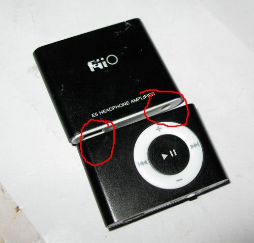
Being bored as usual I started tinkering and what I ended up with is a way to make the smallest possible 3.5mm jack for DIY use in the world. Period. This thing sticks about 3mm out of the female jack when in use, that's it.
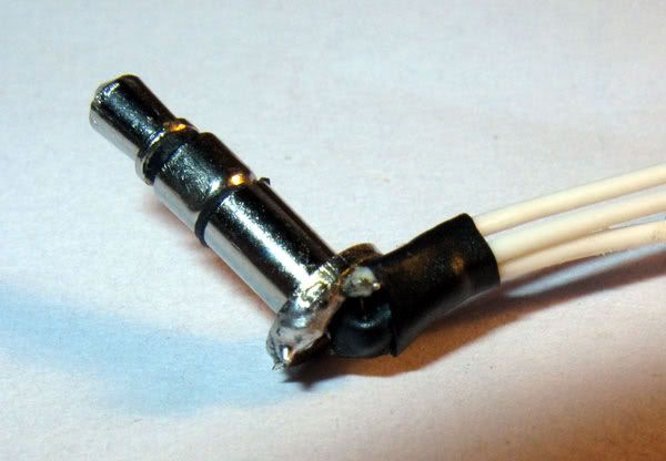
First, you need a smal plug from a IEM or other bought cable that use those plugs, like the one in use on this picture:
http://i136.photobucket.com/albums/q...degard/dxc.jpg
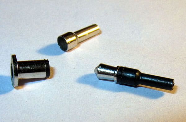
Use a dremel or something the sort and cut the plut by the root, meaning the ground ring. Youll be left with a flat surface with a core (left channel), ring in the middle (right channel) and the ground ring.
Use pliers to carefully drag the plug apart into three pieces: a inner pin, barrel and outer casing:
Cut off the pin 8left channel, inner piece) a bit up from where narrows in to become a pin. Remove the plastic around the part that remains, and solder on a wire, sticking directly out. There is so limited space so that you need to spread the individual wires and lay them around the plug, then solder to make it a "natural" extension of the pin. Cover with heatshrink:
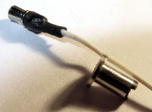
For the right channel, take another wire and remove about half of the individual wire strains if its thickish. Put on a little solder, hold half of it inside the barrel and heat the part remaining outside so the solder on the wire inside the barrel heats up and solders the wire to the inside of the barrel. There has to be enough room left for the wire from the left channl to pass. On the pic, I have more than enough room, but it depends on the wire you use.
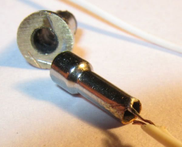
Put the pieces back together. The wire from the left channel goes through the right channel barrel and out, and it all fits back together. Solder the ground wire to the top ring of the plug, and you're all set.
Of course if you do this on the other end of the cable as well, you need to thread on the right channel barrel and ground barrel before soldering the left channel tip. By far the smallest IC in the world if you do that
First, you need a smal plug from a IEM or other bought cable that use those plugs, like the one in use on this picture:
http://i136.photobucket.com/albums/q...degard/dxc.jpg
Use a dremel or something the sort and cut the plut by the root, meaning the ground ring. Youll be left with a flat surface with a core (left channel), ring in the middle (right channel) and the ground ring.
Use pliers to carefully drag the plug apart into three pieces: a inner pin, barrel and outer casing:
Cut off the pin 8left channel, inner piece) a bit up from where narrows in to become a pin. Remove the plastic around the part that remains, and solder on a wire, sticking directly out. There is so limited space so that you need to spread the individual wires and lay them around the plug, then solder to make it a "natural" extension of the pin. Cover with heatshrink:
For the right channel, take another wire and remove about half of the individual wire strains if its thickish. Put on a little solder, hold half of it inside the barrel and heat the part remaining outside so the solder on the wire inside the barrel heats up and solders the wire to the inside of the barrel. There has to be enough room left for the wire from the left channl to pass. On the pic, I have more than enough room, but it depends on the wire you use.
Put the pieces back together. The wire from the left channel goes through the right channel barrel and out, and it all fits back together. Solder the ground wire to the top ring of the plug, and you're all set.
Of course if you do this on the other end of the cable as well, you need to thread on the right channel barrel and ground barrel before soldering the left channel tip. By far the smallest IC in the world if you do that