
Jamdat
New Head-Fier
- Joined
- May 14, 2010
- Posts
- 13
- Likes
- 0
tl;dr Modified a CMoy with TLE2426 which gets super hot. Normal or horrible beginner mistake? Question at bottom and tests/explanation in between.
Hello Head-Fi forums. I've been lurking around here for a while, but now I need to actually ask for help.
I had a need to listen to TV with headphones and this led me to the CMoy amp. I settled on Tangent's helpful tutorial and diagrams since I am coming into this with little electrical knowledge. After buying all the components, I proceeded to royally screw things up by reading the diagrams backwards, getting frustrated with my iron, putting things in backwards and upside down, and completely frying things. It turned out to be such a mess so I threw it all out and started again.
I've done extensive reading of pretty much every page on Tangent's website. I spent lots of time looking at the discussion on virtual grounds(Here). For my second attempt, I decided to slightly modify the CMoy design to incorporate a better ground. So, my design now has a 24V DC rated power source (unregulated) running through a 7824 regulator (the DC adapter puts out 30.2V with no load, so I am above the dropout voltage of the regulator). I then have a TLE2426 (TO-226 3 pin package) splitting the voltage equally. Then I have the op-amp hooked in. The schematic that I have created is below. Yes, that's right, it's just the TLE2426 circuit from Tangent's page mashed into the CMoy circuit like the total beginner I am. I added the 7824 circuit from the datasheet for the part. Is it the best, I have no idea. Does it need more/less components? No clue.

I've laid everything out on a breadboard to test it. I used my computer for a sound source. I plugged the adapter in, clipped alligator clips onto my headphones and sweet, sweet music came pouring out. My mashing in of the TLE2426 worked. I was very happy, listened to an entire song and then... burned myself on the TLE2426!! Holy crap is that thing running super hot!
I then did some experiments with sound on and a multimeter. What I found was that as soon as the sound started, the voltage between the 'OUT' pin and the '-' pin of the DC jack (which was previously 11.85V) was now 19.1V. This got me thinking that there was too much voltage and the TLE2426 was getting hot because of it. So I did some more experiments where I put the ground connections in different places.
Some terminology: I have a 3.5mm cable plugged into my computer. There are three clips attached to it, L, R, and Ground. L and R go into the inputs of the amp. I have called the cable connected to this ground 'Gcp'. The L and R output of the amp is clipped to my headphones. There is another cable clipped to the ground part of my headphone plug. I have called this 'Ghp'.
Gcp = ground from computer jack
Ghp = ground clipped to headphone plug

Now the results of my test:
Gcp disconnected, Ghp connected to Vground: Loud buzz.
Gcp disconnected, Ghp disconnected: very very faint sound. Op-amp is working because it starts crackling when I raise the volume. Op-amp gets hot. TLE voltage is 11.85V.
Gcp disconnected, Ghp connected to '-' DC jack: No sound. op-amp got super hot really fast.
Gcp connected to Vground, Ghp connected to Vground: TLE2426 gets very hot. TLE voltage is 19.3V.
Gcp connected to Vground, Ghp disconnected: Faint sound. Op-amp warm. TLE voltage is 11.85V.
Gcp connected to Vground, Ghp connected to '-' DC jack: No sound. Op-amp got very hot.
Gcp connected to '-' DC jack, Ghp connected to Vground: TLE very hot. Voltage 2.9V.
Gcp connected to '-' DC jack, Ghp disconnected: TLE and op-amp ever so slightly warm. Voltage 11.85V.
Gcp connected to '-' DC jack, Ghp connected to '-' DC jack: Op-amp gets hot. Also sound only comes out one channel.
Judging by my testing, it seems the best is that there should be no ground connection going to the output. But, even with my limited electrical knowledge, this makes no sense to me.
I then hooked up a 9V power adapter (7824 falls out of regulation and has an output of about 7.7V) With this voltage source, nothing gets hot, but the voltage between the TLE 'OUT' and the '-' DC jack is 4.44V instead of the 3.85V like it is with no headphones connected. Everything else is fine (it even sounds ok). It seems that with both power sources, the TLE voltage for common ground (which should be half of the input) jumps up by a big chunk as soon as I plug things into Vground.


Question:
Rounding out my rambling post into a question for more experienced members: Is the TLE2426 getting extremely hot a normal occurance, am I hooking things up incorrectly, or am I doing things really wrong in the schematic? Another option is that my 30V regulated to 24V is just too much for this amp.
Sorry about the long post, but I wanted to give lots of information.
Thanks in advance for your help.
Hello Head-Fi forums. I've been lurking around here for a while, but now I need to actually ask for help.
I had a need to listen to TV with headphones and this led me to the CMoy amp. I settled on Tangent's helpful tutorial and diagrams since I am coming into this with little electrical knowledge. After buying all the components, I proceeded to royally screw things up by reading the diagrams backwards, getting frustrated with my iron, putting things in backwards and upside down, and completely frying things. It turned out to be such a mess so I threw it all out and started again.
I've done extensive reading of pretty much every page on Tangent's website. I spent lots of time looking at the discussion on virtual grounds(Here). For my second attempt, I decided to slightly modify the CMoy design to incorporate a better ground. So, my design now has a 24V DC rated power source (unregulated) running through a 7824 regulator (the DC adapter puts out 30.2V with no load, so I am above the dropout voltage of the regulator). I then have a TLE2426 (TO-226 3 pin package) splitting the voltage equally. Then I have the op-amp hooked in. The schematic that I have created is below. Yes, that's right, it's just the TLE2426 circuit from Tangent's page mashed into the CMoy circuit like the total beginner I am. I added the 7824 circuit from the datasheet for the part. Is it the best, I have no idea. Does it need more/less components? No clue.

The schematic diagram for my modified CMoy.
I've laid everything out on a breadboard to test it. I used my computer for a sound source. I plugged the adapter in, clipped alligator clips onto my headphones and sweet, sweet music came pouring out. My mashing in of the TLE2426 worked. I was very happy, listened to an entire song and then... burned myself on the TLE2426!! Holy crap is that thing running super hot!

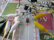
An overview of my breadboard. It is on right now as indicated by the LED.
I got worried, so I did some playing around. I first checked every connection and verified that it was laid out correctly. What I found was that, with no headphones hooked in, nothing got hot at all. Input DC voltage was 30.1V. The voltage coming out of the 7824 (measured from the 'out' pin to the '-' pin of the DC jack) was 23.7V (exactly what it should be). The 7824 was not hot (maybe a bit warm, but barely). The TLE2426 split the voltage exactly down the middle (like it should). Between the 'IN' pin and '-' on the jack was 23.7V. Between the 'OUT' pin and '-' was 11.85V. Perfect. So with no sound hooked up, everything is working out alright.I then did some experiments with sound on and a multimeter. What I found was that as soon as the sound started, the voltage between the 'OUT' pin and the '-' pin of the DC jack (which was previously 11.85V) was now 19.1V. This got me thinking that there was too much voltage and the TLE2426 was getting hot because of it. So I did some more experiments where I put the ground connections in different places.
Some terminology: I have a 3.5mm cable plugged into my computer. There are three clips attached to it, L, R, and Ground. L and R go into the inputs of the amp. I have called the cable connected to this ground 'Gcp'. The L and R output of the amp is clipped to my headphones. There is another cable clipped to the ground part of my headphone plug. I have called this 'Ghp'.
Gcp = ground from computer jack
Ghp = ground clipped to headphone plug

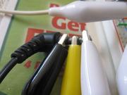
How I connected to my computer. Black=Ground(sleeve). Yellow=Right(ring). White=Left(tip). Gcp is the black connector here.

How I connected to my headphones. Black=Ground(sleeve). Yellow=Right(ring). White=Left(tip). Ghp is the black connector here.
Now the results of my test:
Gcp disconnected, Ghp connected to Vground: Loud buzz.
Gcp disconnected, Ghp disconnected: very very faint sound. Op-amp is working because it starts crackling when I raise the volume. Op-amp gets hot. TLE voltage is 11.85V.
Gcp disconnected, Ghp connected to '-' DC jack: No sound. op-amp got super hot really fast.
Gcp connected to Vground, Ghp connected to Vground: TLE2426 gets very hot. TLE voltage is 19.3V.
Gcp connected to Vground, Ghp disconnected: Faint sound. Op-amp warm. TLE voltage is 11.85V.
Gcp connected to Vground, Ghp connected to '-' DC jack: No sound. Op-amp got very hot.
Gcp connected to '-' DC jack, Ghp connected to Vground: TLE very hot. Voltage 2.9V.
Gcp connected to '-' DC jack, Ghp disconnected: TLE and op-amp ever so slightly warm. Voltage 11.85V.
Gcp connected to '-' DC jack, Ghp connected to '-' DC jack: Op-amp gets hot. Also sound only comes out one channel.
Judging by my testing, it seems the best is that there should be no ground connection going to the output. But, even with my limited electrical knowledge, this makes no sense to me.
I then hooked up a 9V power adapter (7824 falls out of regulation and has an output of about 7.7V) With this voltage source, nothing gets hot, but the voltage between the TLE 'OUT' and the '-' DC jack is 4.44V instead of the 3.85V like it is with no headphones connected. Everything else is fine (it even sounds ok). It seems that with both power sources, the TLE voltage for common ground (which should be half of the input) jumps up by a big chunk as soon as I plug things into Vground.

Blue stripe on bottom=V-, Red stripe on bottom=Jack positive (30V), Blue stripe on top=24V from regulator, Red stripe on top=Vground. Brown jumper carries the regulated voltage.

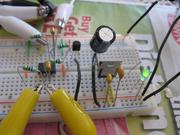
Different view. Right hand white and yellow clips are inputs on pins 3 and 5 of op-amp. Right hand ones are outputs on pins 1 and 7. The optional resistor has been omitted.

Final view. Just for completeness in case somebody can spot an error in wiring.
Question:
Rounding out my rambling post into a question for more experienced members: Is the TLE2426 getting extremely hot a normal occurance, am I hooking things up incorrectly, or am I doing things really wrong in the schematic? Another option is that my 30V regulated to 24V is just too much for this amp.
Sorry about the long post, but I wanted to give lots of information.
Thanks in advance for your help.
")
