Gamma-2 (γ2) DAC Thread
Sep 17, 2010 at 5:39 AM Post #1,981 of 2,154


Quote:
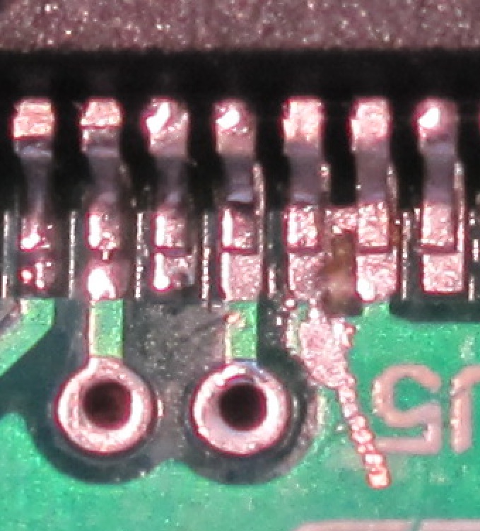
i just rechecked again.the JP2D pin 2 and the 4.5+ pin are reading zero with GND.the others are reading few ohms.
something that i dont understand,i shouldnt hard wire the y1 board right?


Are you measuring resistance? (I assume so if you're saying "ohms")
If that's the case then you have solder bridges causing shorts to ground.
I also asked you to report your voltage measurements according to the initial check procedures.
 
Quote:
something that i dont understand,i shouldnt hard wire the y1 board right?

 
The "initial check" section tells you exactly what you need to do.
 
Sep 18, 2010 at 6:47 PM Post #1,984 of 2,154
sorry for the late response Mr.Ti .i was very busy.i will do the tests first thing in the morning and report back.
 
Sep 18, 2010 at 10:09 PM Post #1,986 of 2,154
If i have a tube amp that can take 3-4 volts of dc offset, would it be better for me to bypass the output capacitors and run dc strait to the amp?  The tube amps driver stage is cap coupled to the output stage.  The driver tube is biased at -7 volts, so the +-2.5v signal with a 2.5v dc off set still leaves 2 volts of head room.
 
Sep 19, 2010 at 12:23 AM Post #1,987 of 2,154
Quote:
If i have a tube amp that can take 3-4 volts of dc offset, would it be better for me to bypass the output capacitors and run dc strait to the amp?  The tube amps driver stage is cap coupled to the output stage.  The driver tube is biased at -7 volts, so the +-2.5v signal with a 2.5v dc off set still leaves 2 volts of head room.


Maybe.  However, a DC offset may shift the operating point of your tube amp input stage enough away from the "center" (0V) to affect its linearity (assuming that the sweet spot is at the center, which may or may not be the case).
 
Sep 19, 2010 at 7:05 PM Post #1,988 of 2,154
Finally had a break in the weather and the humidity dropped by a considerable amount. Still hot, but much more bearable.
 
So, that means I was finally able to access my drill press and assorted power tools and complete my Gamma2/Sigma25 casework:


First time cutting in a snap-in IEC socket. It is mostly straight.  :wink:  Next one will be perfect now that I know what I am doing.


I debated long and hard about bring the filter and clipping switches out the front, but, I figured I would go crazy not being able to manipulate them. At least for an initial listen. So, I might remake the front panel after I determine the setting I like best. I have really been getting into minimalistic panels lately.


In any case, it is finished and sounds great. No hum or buzz that I can hear. The case is sized not only to match up with my other gear, but, also leave room for the inevitable update to the Gamma3 (or whatever follows). I learned that lesson once with the Gamma1.
 
In any case, initial listening is quite positive. Who knows, I might just be able to finally retire the Keces.
 
Sep 20, 2010 at 4:33 PM Post #1,991 of 2,154
$15? That seems a bit high even for the switchcraft one. I'm pretty sure that one is a Neutrik NAUSB, about $4.30 from Markertek. I can't complain about prices myself, as I've spent more than $15 on a power button before
smily_headphones1.gif

 
edit: darn you MisterX....too quick.
 
Sep 20, 2010 at 7:31 PM Post #1,992 of 2,154
It is the Neutrik (available at mouser).


While there is a $6 silver one available, I splurged and bought the $10 all-black one. Call me crazy, I'm like that sometimes.


The goal was an attempt, however impetuous, to future proof the chassis through another DAC upgrade. It also made swapping out of my main two DAC's painless as they both now support B style female jacks. A win for me, YMMV.
 
Sep 20, 2010 at 8:21 PM Post #1,994 of 2,154
Well, what do you know, you are indeed right!
 
I looked up my shipment confirmation:
 
 
[size=small]568-NAUSB-W-B
Neutrik USB & Firewire Connectors
USBA-USB B A
US HTS: 8536.69.4020 ECCN:EAR99
[size=small]1[/size] [size=small]1[/size] [size=small]5.630[/size] [size=small]5.63[/size]
[/size]  
Score!! I am hitting the town big-time tonight!!   
wink_face.gif

 
Oct 3, 2010 at 10:24 PM Post #1,995 of 2,154
Hi Gang,
 
Just finished the y2 to go with the y1 full++.  I am experiencing voltage issues.
I re-flowed U1 and U2.  It did help but it appears I am not getting enough voltage from the Y1.  Y1 was tested and it worked quite nicely with voltages correct at all places.  In looking at u2 the .021 looks like I need to hit it again with solder. 
 
Readings:
 
Bottom 5v = .039
Top 5v = 2.4
 
3.3 v = .019
 
4.5 = 2.38


U1:
 
2.39v  |       |  ?
         |        | 0
2.39v  |       | 2.39v
 
U2:
 
1.19v  |       |  2.39v
          |      |   0v
.021v  |       |  2.39v
 
 VCC= 2.39v
 
If you can point me to the next area to re-flow I would appreciate  it.
 

Users who are viewing this thread

Back
Top