Perhaps, but still a worthy endeavor even if it is unlikely to cure the problem. If you are using stranded hook up wire, you should really consider lightly tinning the wires, especially those that go into the terminal blocks. Those screws can be very hard on untinned stranded wire of that small a gauge. A lot of times, a number of the strands will spread and break right off by the screw action alone. The tinning makes them act a bit more like a solid wire at the connection point and is far, far more mechanically robust.
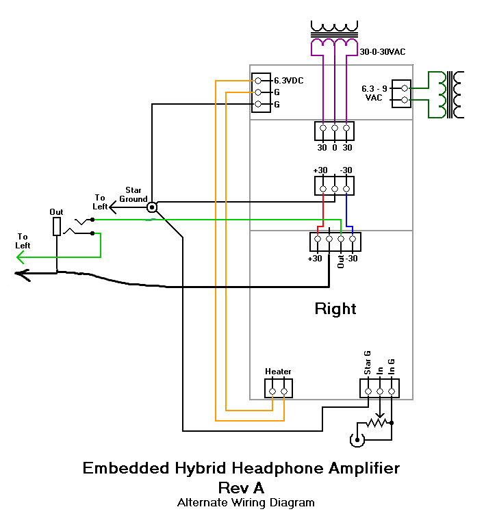
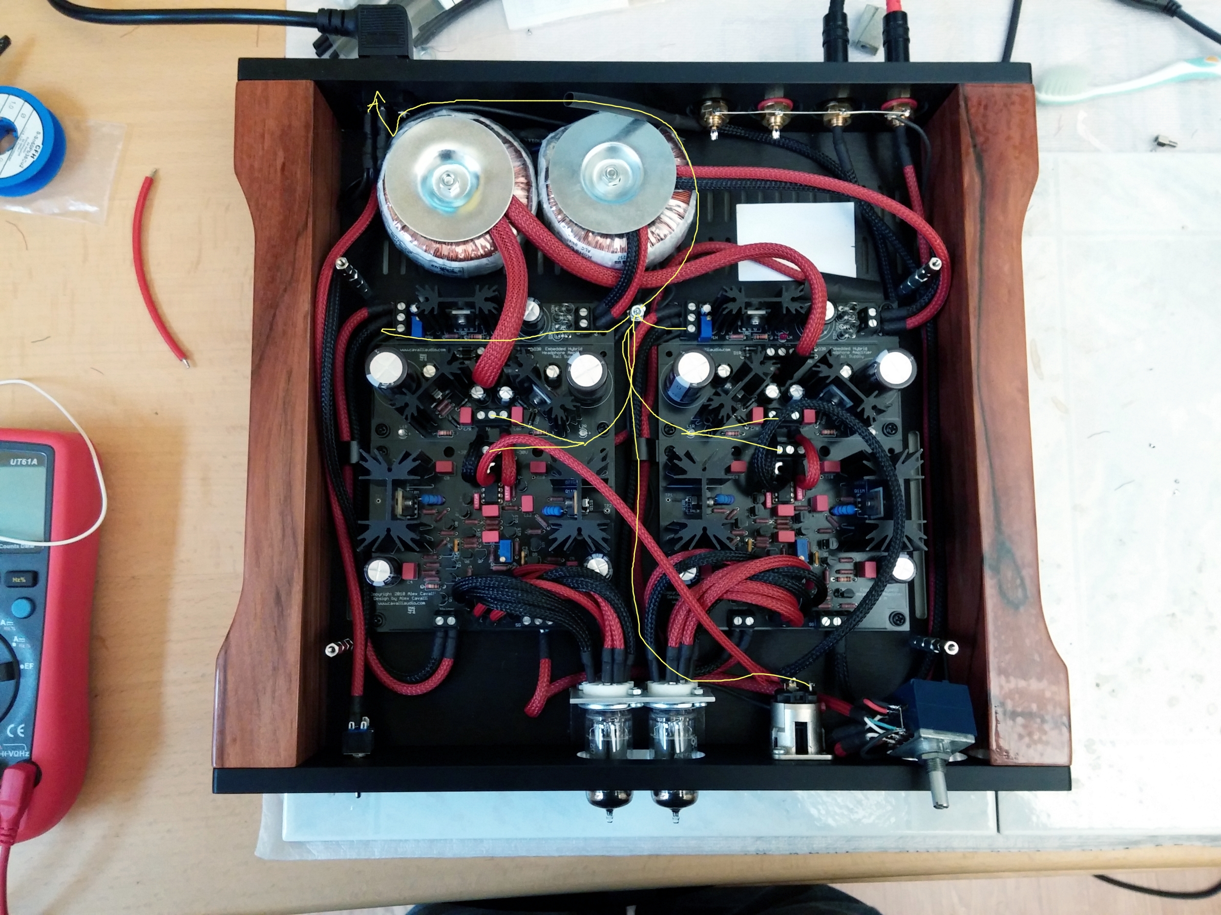
Did you ever fix your ground loop isolation scheme? As it stands now, I am not sure if you have a separate signal ground vice chassis ground. Hence the ground loop. While you are in there, with the power off, use you multimeter and measure the resistance from the star ground to a clear part of the chassis. By clear, I mean an area without anodizing. The anodizing acts as an insulator, so, you need a clear shot to the bare aluminum. Since it does not appear you have drilled into the case yet, sometimes the pem nuts on the bottom plate act as a decent place to measure. Otherwise, if you have attached your safety ground to the case as described previously, that will work perfectly. You want to see if the connection between signal ground and chassis ground is open, shorted or at some resistance in between. Ideally, if the ground loop breaker is installed, the resistance should measure the value of the resistor used for the isolator.
Also, details on how you wired through the attenuator would still be very helpful.
BTW, floating shields do not really act as shields without being tied to a ground source.