Chameleon DAC listening and modifications
May 4, 2010 at 9:48 PM Post #886 of 1,158
Quote:

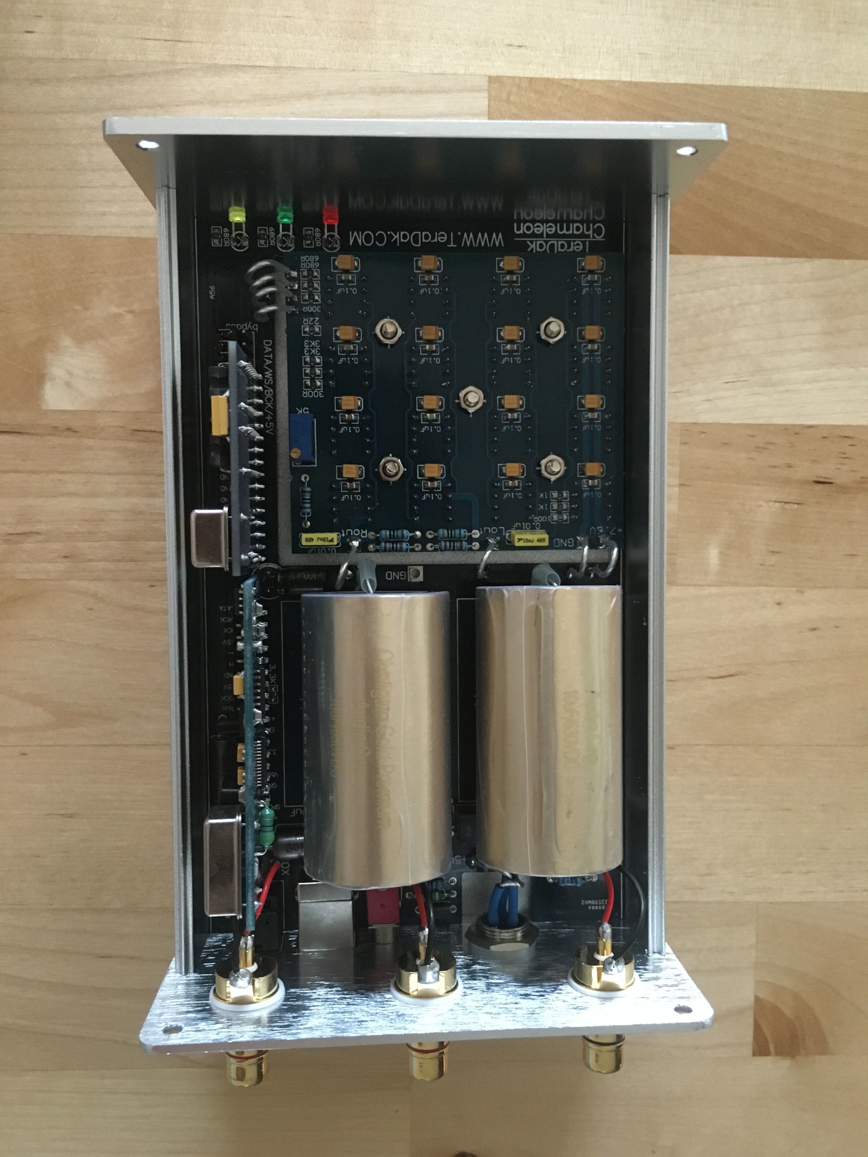
Originally Posted by taiphan /img/forum/go_quote.gif
Thanks, haven't thought of that..

however i got a whole new set of problems.. got my parts today and did the mod, i replaced all the 16 caps on the dac chip and 220R visay naked resistors (same as the texas) with mundorf silver/gold/oil. I solder the output directly to the dac chip and by passing everything else.


after the mod, i was pretty excited to listen to it for the first time however i stuffed up somewhere.. i got MASSIVE distortion!! i can hear the music but it all distorted with noise and no base..

what could possibly caused this? could i have stuff up one of the cap or component with the soldering iron heat? i removed the dac chip when soldering the caps on.

are caps and resistor directional?

can i still hear music if the one of the dac chip is dead?

any advice is greatly appreciated.

Thank you


Yup, 220 ohms is way too high and yes, that will give you massive distortion at the output. If you are using all 16 of the original DAC chips then you need a 160-175 ohm I/V resistor. Anything higher than that and the 8 volts at the DAC chips is not enough. Do not go higher than 7.9-8.0 volts to compensate. Just try a cheap 170 ohm resistor to see if the distortion will go away. It will not sound as good as a nice resistor but you will probably hear that the distortion is now gone. Fine tune to your taste. Try a 165 ohm unit and lower the DAC voltage just a bit to around 7.0 volts to see if you like the sound. Once you have the right value, then get the high quality resistor that you want at the correct value. All will be fine in your DAC then.
 
May 5, 2010 at 9:41 AM Post #887 of 1,158
Quote:

Originally Posted by driguy /img/forum/go_quote.gif
Yup, 220 ohms is way too high and yes, that will give you massive distortion at the output. If you are using all 16 of the original DAC chips then you need a 160-175 ohm I/V resistor. Anything higher than that and the 8 volts at the DAC chips is not enough. Do not go higher than 7.9-8.0 volts to compensate. Just try a cheap 170 ohm resistor to see if the distortion will go away. It will not sound as good as a nice resistor but you will probably hear that the distortion is now gone. Fine tune to your taste. Try a 165 ohm unit and lower the DAC voltage just a bit to around 7.0 volts to see if you like the sound. Once you have the right value, then get the high quality resistor that you want at the correct value. All will be fine in your DAC then.


Yup,

thanks guys, problem solved. Temporarily anyway.

The resistor value was too high, so i removed two dac chip and now it sounds fine now
jecklinsmile.gif


i played around with it, putting 15 dacs in the distortion came back.

after listening for a while, i think 14 chips is still too many for 220r, so 12 it is until the new resistor comes.

another question,

does anyone here bypass the 4.7 mundorf silver/gold/ oil with lower caps? i have 0.022 caps but not sure if the 4.7 needs bypassing, if it doesn't i figure i use these caps to bypass the cheaper caps in my 8 dac valabs.
 
May 5, 2010 at 10:34 AM Post #888 of 1,158
Quote:

Originally Posted by taiphan /img/forum/go_quote.gif
another question,

does anyone here bypass the 4.7 mundorf silver/gold/ oil with lower caps? i have 0.022 caps but not sure if the 4.7 needs bypassing, if it doesn't i figure i use these caps to bypass the cheaper caps in my 8 dac valabs.


Hi Taiphan, I'm sorry for the short reply but I have to leave in a minute. I use Mundorf S/G/O too and bypassed them at first. But it finally turned out that they just sound best when no bypass cap is used. The top-end is very well balanced once burned in completely (it took at least 1000 hours here) and whatever bypass cap I tried the stereo image decreased or became blurry so I don't use them anymore. They are just great without!
 
May 5, 2010 at 11:59 AM Post #889 of 1,158
My Chameleon has arrived at long last! Now I have to go back and re-read the whole thread. Damn!
Anyway, I have done the yellow wire mod, and have run in the dac for 40 mins. Is it ready yet?
Seriously though, Blackgate FKs are pretty hard/expensive to get, would it be worth trying 10uf Silmic IIs on the chips? I want to save my limited cash for Texas resistors, output caps/transformers etc.
 
May 5, 2010 at 12:26 PM Post #890 of 1,158
No need but putting up with them while they burn in is a drag.
for me I get a top end sibilance and image parallax that distracts. Like looking through old poured glass walking down a halway. Keeps changing. argh.

But the rest of the band is cohesive enough. I swapped my ol VALAB back in just to see if it is not the transport and nope, the Mundorfs still need more time and I've had them in there for a month at least.

As for part selection, I would spend the most money you could at each point. You will realize the impact each time, it will feel worth it, and when you are done you will have no regrets. But most expensive is not always best. I went with steel for the OPT transformers and I am staying put.
 
May 6, 2010 at 2:31 PM Post #891 of 1,158


Quote:
Hi Bill, great work pushing the thread along as always. As a kind of Messenger Service
wink.gif
for all of the curious here, I have to ask the question if you are tempted, at all to give interstage transformers a go, for coupling; now that Pats cracked that one wide open?


Yes this is on my "to do" list. However I am only interested in Silver wound output transformers and they are going to be hard to come by. I will eventually get this done and report back.
 
May 6, 2010 at 3:24 PM Post #892 of 1,158


Quote:
My Chameleon has arrived at long last! Now I have to go back and re-read the whole thread. Damn!
Anyway, I have done the yellow wire mod, and have run in the dac for 40 mins. Is it ready yet?
Seriously though, Blackgate FKs are pretty hard/expensive to get, would it be worth trying 10uf Silmic IIs on the chips? I want to save my limited cash for Texas resistors, output caps/transformers etc.


silmic II are great alternatives to Blackgates, very musical, I would up the uf from 10uf to 47uf though, the .1uf smd caps handle the fast discharging, the 47uf will give the oomph!  I'm listening to my Valab at the moment, whilst my Chameleon input board is being Hifaced, by jkeny, and I had forgotten how damn good that dac is. And my Valab has silmic II 47uf for decoupling caps! For the ultimate transparency go for Blackgate FK (dont bother with Blackgate standard) though not only are they more expensive, their honesty, paradoxicaly, can sometimes make the sq worse, (the reason, I believe, why  there are those who dont like them) unless, of course, the rest of your gear is up to scratch. Also BG need a good month to burn in, and its not a pleasant experiance right up untll the end, the silmics are good in 2 weeks and sound pretty good after a few days.
 
May 6, 2010 at 5:25 PM Post #893 of 1,158
As Wood says, I have received his USB/SPDIF daughterboard & I wanted to ask a couple of questions to the accumulated knowledge base that is represented here. Forgive me if these Qs have been asked before, there are just too many pages to read through. I would normally trace the signals I'm asking about but Woods board is, ahem, crowded :)
 
- I was thinking about disabling the Tenor chip as it then removes any self generated noise it might be putting into the PS & also stops any interaction with the clock whch also feeds WM8805 SPDIF receiver. So first there seems to be a SPDIF output from pin 27 TX of the Tenor chip - is this routed to anywhere (I see SPDIF spots on the back of the board?)
 
- The Tenor chip is fed by U202 3.3V regulator but unfortunately there are no component codes on the silk screen - which reg feeds the Tenor chip - the one on the clock side of the board (which I presume) or the other side?
 
- Are there any other issues with disabling the Tenor chip that I'm not aware of?
 
Although I'm not doing anything with it, has anybody considered the impedance of the SPDIF input circuit - just putting a 75R across the SPDIF transformer primary does not mean it's 75 ohm impedance or maybe it does?. What looks wrong here is that the grounding on both the primary & secondary leg of the SPDIF transformer is not the best configuration - no true galvanic isolation
 
Again, apologies if all this been discussed before!
 
May 6, 2010 at 7:25 PM Post #894 of 1,158

 
Quote:
Quote:

Originally Posted by driguy /img/forum/go_quote.gif


Has anyone here bypass the 4.7 mundorf silver/gold/ oil with lower caps? i have 0.022 caps but not sure if the 4.7 needs bypassing, if it doesn't i figure i use these caps to bypass the cheaper caps in my 8 dac valabs.

IMO & IME you do not need to bypass the Mundorf caps. I have used them as coupling caps in my preamp and they sound really nice. If they sound harsh you probably have issues elsewhere. Bypassing very high quality caps like this in the signal path is really not a good idea. I have explained why in one of my previous posts.
 
 
May 7, 2010 at 4:27 AM Post #895 of 1,158

 
Quote:
silmic II are great alternatives to Blackgates, very musical, I would up the uf from 10uf to 47uf though, the .1uf smd caps handle the fast discharging, the 47uf will give the oomph!  I'm listening to my Valab at the moment, whilst my Chameleon input board is being Hifaced, by jkeny, and I had forgotten how damn good that dac is. And my Valab has silmic II 47uf for decoupling caps! For the ultimate transparency go for Blackgate FK (dont bother with Blackgate standard) though not only are they more expensive, their honesty, paradoxicaly, can sometimes make the sq worse, (the reason, I believe, why  there are those who dont like them) unless, of course, the rest of your gear is up to scratch. Also BG need a good month to burn in, and its not a pleasant experiance right up untll the end, the silmics are good in 2 weeks and sound pretty good after a few days.

Thanks, I have to limit my costs, as I have other expensive hobbies!
 
 
May 7, 2010 at 1:00 PM Post #896 of 1,158
Bill, you might just want to get in touch with   www.tribute-audio.com as I think he might be able to help you out in this one...
 
Jkeny; I'd honestly expect those transformers to be auto-trannies so not representing true galvanic isolation anyway..
 
May 7, 2010 at 5:34 PM Post #897 of 1,158


Damn I just lost everything I just wrote when a PM came in ... this new forum format has issues. Ok here goes again.
 
After reading the comment from jkeny I decided to have a closer look at the input board as I now have a spare one. What I discovered is that our FIM is not really floating even though it measures that way with my Fluke meter. Pin 2 is still hooked to ground via a trace under the number 5 above. Woops! I tried removing the riser pins as you can see but that was to much trouble, it's easier to simply cut the trace with a razor blade. While your at it,  I also suggest cutting the Spdif input trace under the number 2. (You could also just cut the riser pins but I don't like the ideas of those little antenna's waving in the wind.)
 
This was a really nice sonic upgrade, my Spdif Chameleon now sounds much closer to my I2S Chameleon. If the FIM is your thing, take the 3-4 minutes and cut your traces. Nice!
 
Thanks jk.
 
May 7, 2010 at 7:11 PM Post #898 of 1,158
There you go, Bill, glad it sounds better but I think you might have a problem - you cut the wrong trace & removed the main ground connection of the board.
 
Now a real SPDIF upgrade would improve this further but I'm keeping that one for a possible SPDIF replacement  board that you guys might be interested in.
 
Since receiving Woods board & analysing it, I would implement the SPDIF much more optimally than the current arrangement & with some tricks added too.
 
Anyway, I've finished Woods board modifications for Hiface I2S integration so no need to rush to answer my questions above
confused_face_2.gif
 I won't tell you any of the details on this work but it should be surprising. Sending it back to him tomorrow. 
 
May 7, 2010 at 8:20 PM Post #899 of 1,158
The question: Is the Spdif input of the Chameleon 75 ohms by simply putting that surface mount 75 ohm resistor between pins 1&2 on the Pulse transformer. Probably not as true impedance is a complex relationship between the Pulse transformer, jacks, cable and source … but that 75 ohm resistor has to be in the circuit somewhere to load the cable. 75 ohm cable does not actually measure 75 ohms.

Wiki says:
“Each type of coaxial cable has a characteristic impedance depending on its dimensions and materials used, which is the ratio of the voltage to the current in the cable. In order to prevent reflections at the destination end of the cable from causing standing waves, any equipment the cable is attached to must present an impedance equal to the characteristic impedance (called 'matching'). Thus the equipment "appears" electrically similar to a continuation of the cable, preventing reflections. Common values of characteristic impedance for coaxial cable are 50 and 75 ohms.”

Some say BNC connectors creates less issues and remains closer to the ideal 75 ohm load vs. using RCA jacks. Maybe that is true with so called 75 ohm coax cable but what about different cable topology. I have tried a boat load of different Spdif cables and only a couple actually sounded better than the rest, none of them a 75 ohm coax design.
It’s a black art.

Same goes with I2S … but that’s not going to stop me from trying.


Users who are viewing this thread

Back
Top