cap suggestions for 0404
Mar 29, 2005 at 4:55 PM Post #46 of 56
Quote:

Originally Posted by lan
They don't really state which OSCON or blackgate series they used though. From the pictures, the OSCONs aren't purple??? and the blackgate looks like the standard one not n / nx / hiq.


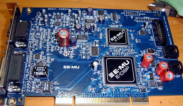
True, but the pictures for me show purple oscons (monitor settings?).. Also check the lettering, definitely oscon style letterings. Also: http://diyparadise.com/oscon.html
 
Mar 29, 2005 at 5:03 PM Post #47 of 56
I'm not doubting they're oscons. I'm just wondering the series. Maybe it's an old one.
 
Mar 31, 2005 at 10:52 AM Post #48 of 56
pics:
0404bg-front.jpg

0404bg-back.jpg


took sleepdan's suggestion's thats why there're those huge 1000uF caps at the back. I'm just wondering, will these large caps "slow" the sound down since they'll take longer to charge/discharge?
 
Apr 3, 2005 at 7:13 PM Post #49 of 56
ftp://blomquist:weissi@members.chello.at/0404.JPG

this is my modded 0404

missing some parts on the photo....

On the right, you can see 2 additional Voltage regulators - one is dedicated for the crystal oscillator (actually, if you look closer you might see that i simply stacked the additional Reg on the original one), the 2nd for the frequency multiplier (ICS525...) (2x AM1117 -3.3) Capacitors there are OS-CON´s and 10µF Ceramic cap´s from a socket 939 Mobo :wink:

The original 78M05 has been replaced wth a REG104-5 from TI;

around the DAC: added ferrite beads, OSCON´s on the backside and of course the 10µ ceramic cap´s;

Buffer opamps replaced by AD8022´s (with dedicated 100nF caps) & lower output resistors (now 700 OHM) coupling caps are now 100µ/25V Panasonic FC (they definately have their very own sound - I like their sonic performance)

Output opamp is a AD8397;

+-12V rails: removed the 4.7 Ohm damping resistors with ferrite beads; 820µF/25V Rubycon KZE extra-special low ESR Mobo caps (Oh yea, I´ve killed 3 Mobos in the last 2 months
icon10.gif
)

But sorry, I cannot say if it sounds better yet - haven´t got my K271 from the screwing ebay seller - He has been banned and my 99 Euros are probably gone :frowning2:

ahh, this is silicone addhesive around the IC´s - prevention, you know
 
Apr 4, 2005 at 5:04 PM Post #50 of 56
listening test accomplishes successfully :)
big improvement in terms of details/seperation...

All I can do is to suggest you the seperate Voltage regulators for the crystal oscillator & the ISL525 !! this is definetly worth it (If you pay a car for the BG´s...)
Next step would be a dedicated reg for Vdd/DAC..
Would be nice to hear from you!
 
Apr 5, 2005 at 12:03 PM Post #51 of 56
Hi Blomqvist,

interesting stuff! Your poor 0404 though ... I almost feel sorry for it!

My card should be turning up soon, and I'll be doing some mods to it.

I noticed you swapped the 4r7 resistors for ferrite beads. I'd be concerned that they form a sharp resonance peak with the 820uF caps due to their low ESR. I may put in an inductor with ESR around 10ohms to damp the resonance. I'm also thinking of bypassing the analog stage altogether and feeding a balanced output to my amp somehow, and adding a balanced input - possibly a transformer - there.

I'll follow your suggestions re. adding regs to the clocking circuitry, probably lt1763s. What is the freguency of the oscillator by the way? It's tempting to add a new clock altogether and feed it directly to the AK4395 - would have to let software take care of feeeding the card with the correct sample rate then.

Keep us informed of any more work you do.
 
Apr 5, 2005 at 1:13 PM Post #52 of 56
Yes, the low ESR Cap isn´t that good there... I do hear my hdd working when attenuators are at 0dB... Have to by me headphones today (old ones died
rolleyes.gif
with the dead of my THS6012 - hehehe) wich one should I take ?? K240S or K271S ?? only AKG, Austria you know :wink:

Haven´t had a look into the datasheets yet but I think that the 10µF ceramic caps works better than a combination of e.g. 33µF OSCON and 100nF ceramic cap

And hey, this is no beauty contest here...
rolleyes.gif
My hole computer stuff looks like that
cool.gif


hmm, frequency was ~24,...MHz I think...

Btw. do you think that higher frequency (DDR-clk, HTT-clk, etc...) appear significantly at the PCI-bus?
 
Apr 5, 2005 at 6:24 PM Post #53 of 56
Quote:

Originally Posted by blomquist
hmm, frequency was ~24,...MHz I think...


That'll be 24.576 then ... easy to get low jitter modules at that frequency. Valpey-Fisher units are good, apparantly, as well as Guido Tent's of Tent Labs.

Quote:

Originally Posted by blomquist
Btw. do you think that higher frequency (DDR-clk, HTT-clk, etc...) appear significantly at the PCI-bus?


I've not taken a 'scope to my PC, but I'd be surprised if those +/- 12v lines weren't pretty ugly. It's a shame soundcards don't have power connectors like modern graphics cards - you could rig up a low noise linear PSU easily and fit it in the case.
 
Apr 5, 2005 at 8:17 PM Post #54 of 56
Yeah, at first I was concerned about feeding the opamps with the dispised +-12V from the smps... as far as I realized now, this doesn´t seem to have a bad impact on the performace... (why did I then solder the Rubycon KZE in there??)
I have to say that all that opamp changing and +-12V supply conditioning didn´t improve the sound as the seperate power supply for the clock circuits did... But that may all be placebo since I haven´t had Headphones for the last month and all listening was done on my buschhorns (+mixer +Gainclone...)
My hole modding was done really uncoordinated, I bought K271´s today - and now the hole thing sounds just so sweet....
smily_headphones1.gif
 
Apr 6, 2005 at 11:44 AM Post #55 of 56
Quote:

Originally Posted by blomquist
Yeah, at first I was concerned about feeding the opamps with the dispised +-12V from the smps... as far as I realized now, this doesn´t seem to have a bad impact on the performace... (why did I then solder the Rubycon KZE in there??)


I'll have to do some before and after measurements on the +/-12V lines with a 'scope. See how it correlates with RMAA and listening tests.

Quote:

Originally Posted by blomquist
I have to say that all that opamp changing and +-12V supply conditioning didn´t improve the sound as the seperate power supply for the clock circuits did.


EMU specify <1nS jitter for this card, which frankly is crap. A good CD player will be looking at 200pS or less. I'm sure there are big gains to be found by improving the clocking on this card, as you've found.

A fairly simple experiment would be to bypass the PLL chip, and feed the DAC (plus whetever else needs it) directly from the clock. 24.576MHz corresponds to a sample rate of 96KHz, so then simply upsample everything going into the card with Foobar or whatever. Hopefully I'll get the time to put all these thought experiments into practice!
 
Apr 6, 2005 at 2:13 PM Post #56 of 56
Bypassing the pll vs. lost of hardware effect doesn´t work for me :)

P.S.: Another option: desolder the muting transistors...
 

Users who are viewing this thread

Back
Top