


scootsit
1000+ Head-Fier
- Joined
- Oct 23, 2011
- Posts
- 1,166
- Likes
- 41
Hello All!
I recently built a distribution amplifier for my friend's studio. It wasn't too complicated or anything, but this is my first fairly real build (aside from a CMoy or two), so I thought I'd share some pictures and what not. I have to say, that a lot of people in and around this forum provided a lot of help and input. My background is not in electronics, so I appreciate that help.
The design is based heavily on the CMoy.
I started with the power supply. Given my limited experience, I was going to use batteries, but that seemed like it would be a pain in a studio setting. So, I looked for a linear regulated power supply. The AMB Sigma25 looked pretty simple (http://www.amb.org/audio/sigma25/), so I used that schematic and built it on a piece of Radio Shack stripboard.

Mounted perpendicular to the board is the rail splitter. It is built on a piece of broken Radio Shack protoboard. I used the TLE2426 with noise cancellation, as per Tangent's seminal schematics (http://tangentsoft.net/elec/vgrounds.html).

Four of those made up the total power supply for the unit. The transformer was from Radio Shack as well, and puts out 12VAC, 450mA, and is housed in a separate case (see last picture).
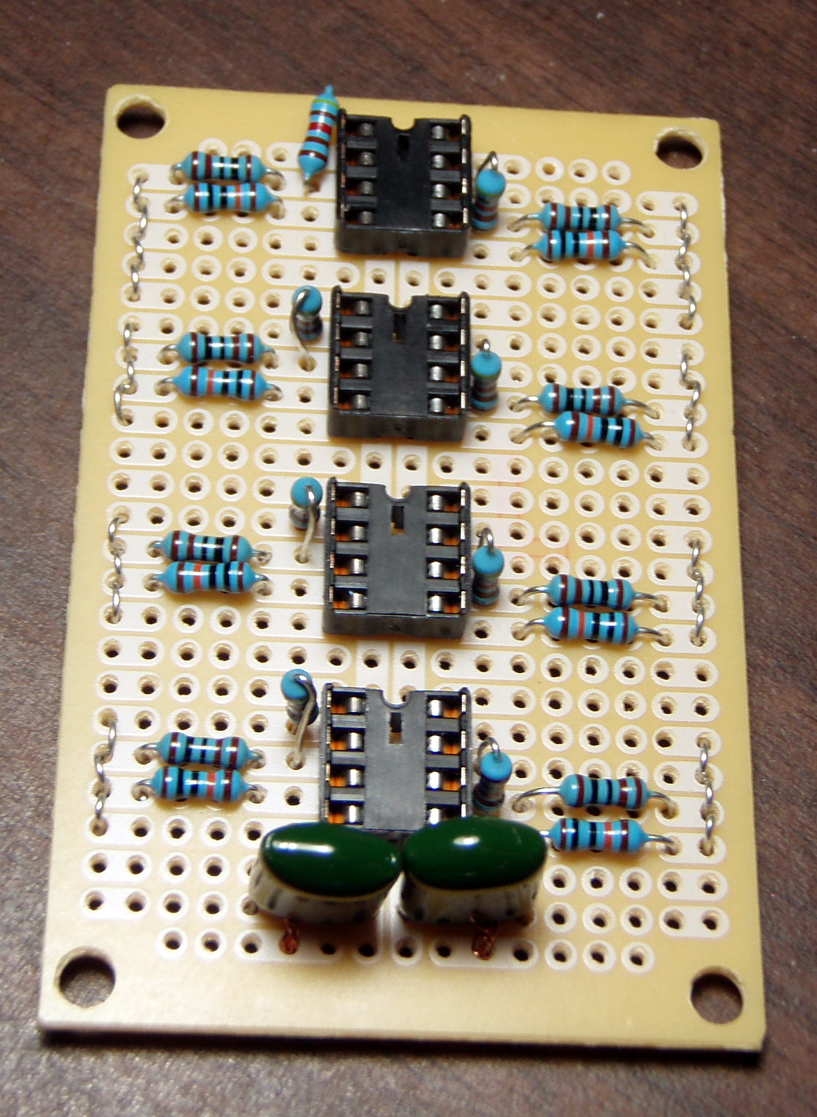
Once I had the regulator and rail splitters done, I began working on the amplifier board.

This is very similar to the CMoy lay out, but with a gain of four, and obviously, it has four op-amps. I chose to use the TS922 by ST. I then soldered on the leads.

I then connected the board to the power supply, rail splitters, outputs, and pots.

Mounted it in the case.

Here's the (almost) finished product. The alligator clip will go away once I get the right drill bit to mount the switch that will go there.

The case, knobs, pots, etc are all from Radio Shack as well.
And finally, with the transformer.

I should also thank Howard (Fred_Fred) for turning me on to Google DIY board creator, and providing some very helpful feedback. BinaryMike over on Audiokarma was also really helpful, so thanks a lot! I know this isn't a particularly exciting build or anything, but it was for me.
The result is excellent sound quality. There are a few caveats. You probably noticed the lack of a buffer. That was intentional (sort of). I'm planning on using this as the second stage, following the Oatley K272 preamp, which has a buffered output. I may decide to leave the K272 out, in which case, I will add a buffer with some unity-gain stable chip. I have a few OPA2107s laying around, so maybe one of them.
Anyway, I had a lot of fun, made a few mistakes and most importantly, learned a TON.
Thanks!
I recently built a distribution amplifier for my friend's studio. It wasn't too complicated or anything, but this is my first fairly real build (aside from a CMoy or two), so I thought I'd share some pictures and what not. I have to say, that a lot of people in and around this forum provided a lot of help and input. My background is not in electronics, so I appreciate that help.
The design is based heavily on the CMoy.
I started with the power supply. Given my limited experience, I was going to use batteries, but that seemed like it would be a pain in a studio setting. So, I looked for a linear regulated power supply. The AMB Sigma25 looked pretty simple (http://www.amb.org/audio/sigma25/), so I used that schematic and built it on a piece of Radio Shack stripboard.
Mounted perpendicular to the board is the rail splitter. It is built on a piece of broken Radio Shack protoboard. I used the TLE2426 with noise cancellation, as per Tangent's seminal schematics (http://tangentsoft.net/elec/vgrounds.html).
Four of those made up the total power supply for the unit. The transformer was from Radio Shack as well, and puts out 12VAC, 450mA, and is housed in a separate case (see last picture).
Once I had the regulator and rail splitters done, I began working on the amplifier board.
This is very similar to the CMoy lay out, but with a gain of four, and obviously, it has four op-amps. I chose to use the TS922 by ST. I then soldered on the leads.
I then connected the board to the power supply, rail splitters, outputs, and pots.
Mounted it in the case.
Here's the (almost) finished product. The alligator clip will go away once I get the right drill bit to mount the switch that will go there.
The case, knobs, pots, etc are all from Radio Shack as well.
And finally, with the transformer.
I should also thank Howard (Fred_Fred) for turning me on to Google DIY board creator, and providing some very helpful feedback. BinaryMike over on Audiokarma was also really helpful, so thanks a lot! I know this isn't a particularly exciting build or anything, but it was for me.
The result is excellent sound quality. There are a few caveats. You probably noticed the lack of a buffer. That was intentional (sort of). I'm planning on using this as the second stage, following the Oatley K272 preamp, which has a buffered output. I may decide to leave the K272 out, in which case, I will add a buffer with some unity-gain stable chip. I have a few OPA2107s laying around, so maybe one of them.
Anyway, I had a lot of fun, made a few mistakes and most importantly, learned a TON.
Thanks!
