AD8397-class A?
Jul 28, 2006 at 4:14 PM Post #16 of 26
You do seem to be stuck conceptually here on the idea that fets are the only current sources in the world and that you even want a ccs for Class A bias for full range output drive

A ccs loading a op amp creates a single ended Class A output with only 25% efficiency of peak output power to static dissipation ratio – measure output in rms W and efficiency drops even more – ½ of the static power is wasted heating up the op amp, the op amp sees even worse dynamic current demands as it has to supply 2x current on positive peaks – both the load and the ccs current (sink)

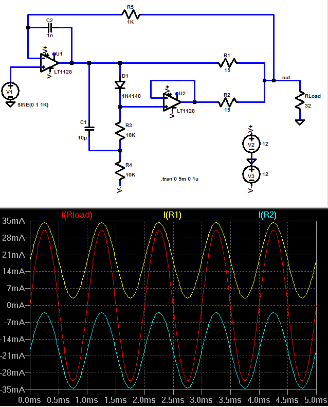
Class A bias can also be done push-pull – each of 2 amplifying devices see ½ the peak load current at rest, each device current changes linearly as the output moves, one increasing, the other decreasing so that at full swing one device just reaches 0 current as the other supplies all of the load current

Push-pull Class A is 50% efficient from peak power to static and requires each device only be biased at ½ the peak current and dissipate only ½ of the peak rated power – much easier if heat removal is your limitation

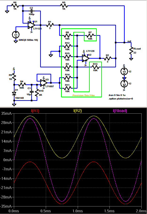
A op amp push pull class A can be done with the A47 style parallel scheme – just introduce a floating voltage source in series with the “slave” op amp’s input to offset the 2 op amp outputs to get the desired current thru the resistors that sense and add the outputs – the approach I used

ClassApp.png
 
Jul 28, 2006 at 11:31 PM Post #18 of 26
seems likely doesn't it...

but I'm not willing to post the full schematic - at 100+ smt parts/channel on both sides of a 4 layer board I doubt many here would get it to work - this is very much an experimental prototype and far from a DIY construction project - and I might prefer presenting the unique multiloop feedback idea in a more formal setting

I may give more details of the TPA "totem-pole" cascade power output stage later if people are interested - although it has unique stability limitations of its own too that will probably prevent much DIY use

the above LtSpice "sketch" demonstrates the principle I used for Class A bias in my amp
 
Jul 31, 2006 at 3:17 AM Post #19 of 26
my TPA6120 multiloop Class A parallel/cascade opened up on bench - how it usually runs for debugging/mods

side view shows thermal path stackup:

stack.jpg


AD8397 package is smaller but likely it is possible to suck enough power out with a similar approach that at least the push-pull Class A scheme I use could work over some range - someone else has reported using them upside down with Cu sheet(flashing?) "U" glued to their EPADs
 
Aug 1, 2006 at 8:11 AM Post #20 of 26
Dang JCX, nice work. I should dig around and see if I can find one of my nice Panaflo orb heatsinks (those are the ones that got the whole "orb" heatsink thing started ~10-12 years ago). I keep thinking about using them to cool a gainclone... Never thought I'd see one used on a headphone amp
biggrin.gif
 
Aug 16, 2006 at 2:47 AM Post #21 of 26
Dear jcx,

you wrote: "I may give more details of the TPA "totem-pole" cascade power output stage later if people are interested - although it has unique stability limitations of its own too that will probably prevent much DIY use"

I am surprised that nobody has taken you on the offer. I for one would be extremely interested in your implementation of the multiloop concept, having read all you have published about it on various forums, especially because you are using amplifiers in both loops instead of the (questionable?) amplifier-follower configuration.

Thank you,

M
 
Aug 16, 2006 at 2:58 AM Post #22 of 26
Quote:

Originally Posted by mefistofelez
Dear jcx,

you wrote: "I may give more details of the TPA "totem-pole" cascade power output stage later if people are interested - although it has unique stability limitations of its own too that will probably prevent much DIY use"

I am surprised that nobody has taken you on the offer. I for one would be extremely interested in your implementation of the multiloop concept, having read all you have published about it on various forums, especially because you are using amplifiers in both loops instead of the (questionable?) amplifier-follower configuration.

Thank you,

M


I'm surprised as well. I'd have been willing to try it ;D
 
Aug 17, 2006 at 1:12 AM Post #23 of 26
[a little revisioning - moved this post which really addresses this thread's title to here from the "Designing a Amp" thread]

This sim shows how you could make a multiple-input differential “instrumentation” op amp circuit to perform the same Class A bias trick with AD8397 op amps which do not have rail-to-rail inputs

The circuit is designed so that the AD8397 op amp U2 inputs only swing ~ ½ the rail voltage and uses all equal value precision resistors in the critical diff gain setting resistor network

An added advantage is that the bias setting V source doesn’t have to float and could be common between channels – simultaneously trims both channels and allows a single Class A bias on/off switch

R1 is the “master” output current sense resistor driven by U1, R2 is the “slave” current sense resistor

U2’s R network forms a differential input “instrumentation” amp which measures R1’s voltage drop and references it to the output node, applying the diff + the offset from U3 bias source to R2

The sim uses the LT1128 since it comes with the LtSpice and can output ~ 30 mA – enough to swing 1 V on the 32 Ohm load for demonstration purposes U1,2 of course should be AD8397 in the real circuit and the bias bumped up to ~ 50 mA for +/- 100 mA, 3.2 Vpeak drive with 6 cell battery power


ppclassA.png


A cost is the precision required for the diff amp resistors – but what self respecting audiophile doesn’t spend more on resistors than the active components in their amp?

the attachment is the LtSpice .asc - just rename without the .txt and run in the free Linear Technology SwCAD III Spice


the "totem-pole" or cascade design I used for my proto's high V swing output should probably go in another thread - maybe I''ll do that sooner now
 
Aug 21, 2006 at 7:40 PM Post #25 of 26
Big OT here:

Quote:

Originally Posted by jcx
The heat sink is a Zalman Golden Orb II, drilled and tapped for a ¼-20 ss socket head screw which protrudes from the center of the Cu slug bottom and to which the pcb carrying the TPA6120s is clamped


Actually, that's a Thermaltake Golden Orb II.. Zalman flower heatsinks don't use a slug with aluminium radian-crotch fins like that.. They clamp thin copper and/ or aluminium sheets together and fan them out into a orb design..

Quote:

Originally Posted by motherone
Dang JCX, nice work. I should dig around and see if I can find one of my nice Panaflo orb heatsinks (those are the ones that got the whole "orb" heatsink thing started ~10-12 years ago). I keep thinking about using them to cool a gainclone... Never thought I'd see one used on a headphone amp
biggrin.gif


Yep.. Panaflo 'orbs' on the DEC Alphas which led to Artic Agilents then to the ThermalTake Golden Orb, Blue Orb Dragon Orb & what not... The Tt products were infamous core-crushers back then..
 
Aug 22, 2006 at 12:10 AM Post #26 of 26
Yes, Thermaltake - my mistake, maybe poor branding? not that I ever followed cpu heatsinking, just saw store display

in any event I selected this Golden Orb heatsink for the Cu slug to quickly spread the heat from "over clocked" TPA6120 running at ~7.5 W per pkg to widely spaced fins that looked like they would work in convection without the fan - seems to be fine in this app, I measured < 1.5 degree C/W without the fan which is fine for my 25-30 W total heat load

to return to the thread topic it isn't necessary to go to such extremes if you match supply V and load impedance a little better while running the ad8397 in true Class A for the full output swing

nominally you only have to dissipate ~ as much quiescent pwr in push-pull Class A as you want to deliver to your load (with peak to rms and V swing issues maybe quiescent * 1/2 => rms pwr to load is a better estimate)

the ad8397 could handle 2 W pwr diss per pkg with a good EPAD pcb plane heatsinking scheme - this would allow 1 Wrms/channel to the load, enough headroom for many cans in full output Class A operation if you match the supply V to the impedance without my extreme heatsinking measures
 

Users who are viewing this thread

Back
Top