


In preparation for my incoming CEntrance HifiM8, I decided to try my hand at making a Micro USB B OTG to USB B cable so that I can use my Galaxy Note II as my transport.
It turned out alright (confirmed to work with my Note II and my Nuforce HDP) so I decided to post this tutorial for anyone with an Android device that is USB OTG capable for use with outboard DACs.
Please forgive me for not having more pictures - I always forget to document things until I am half way through.
DISCLAIMER: This info is only for the connectors that I used. I am also human and might have mislabeled something. Always verify my info with what you know and find out about the connectors that you use.
1. Obtain Micro USB B connector. I got mine on ebay. While this listing isn't the one I bought (can't find the original), these look like they should work: http://www.ebay.com/itm/DIY-Micro-USB-Type-B-Male-5Pin-four-piece-assembly-Connector-black-color-10pcs-/160922939469?pt=US_Cell_Phone_PDA_Cables_Adapters&hash=item2577c1304d
2. Obtain USB B connector. I harvested mine from a monoprice cable (use heatgun to soften molded cover and remove with pliers and a cutter). You can get them at any electronics shop like Mouser or if you want a pretty gold plated one, Doublehelixcables had them at last check.
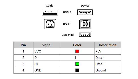
3. Link pin 4 and 5 on the Micro USB B connector. This short will let the Android device recognize the cable as an OTG cable and treat whatever is on the other end accordingly.

The picture above shows the pins (4 and 5 linked with a small jumper of wire) on the connector I used (not guaranteed to match, please check whatever documentation you get for your connector or check for continuity using a multimeter). The red arrows are pointing to the three pads on top, the blue indicates the that the other two pads are on the bottom. They alternate top and bottom.

Another shot showing the jumper and a better idea of where the bottom two pins are.
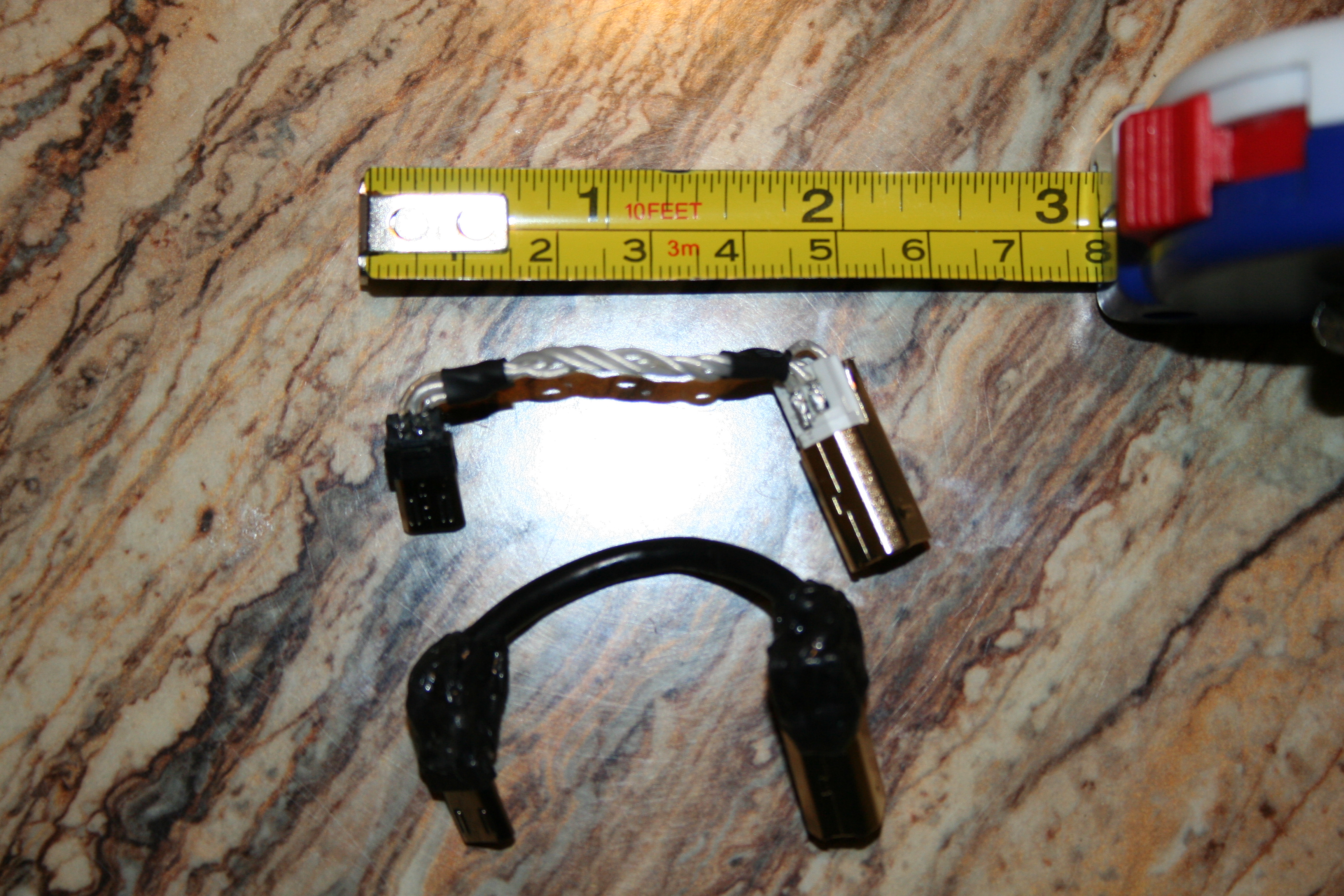
4. Carefully plan out the length of your wires, as there isn't a lot of room or margin for error. The pads for soldering are very close together so also be careful about how much solder you use and how thick a wire you use. You can see how 26awg fits from my pictures (might be as large as I would go).
5. I started the wiring from the USB B side since it easier to anchor and needed the most thought for placement of wire. I chose to have the wires come out of the top based on the layout of the M8.

Here is the USB B with the wires attached already at their respective spots. Again red indicates on top, blue on bottom.
6. Depending on the USB B connector that you get, you will have to cut down the shield to keep the cable as low profile as possible. I had some tin snips that I used to cut mine down to size.
7. At this point, you could braid your wires, but for me, for such a short cable with such small connecting points, I figured it would be more trouble than it is worth to do so. A simple twist should work fine.
8. Here is a picture showing everything wired up but with a couple labels added:

(sorry, didn't take a picture of the underside, but it should be straight forward at this point)
9. At this point, recheck pinouts and continuity to make sure you have the pins linked to the right pins on the other connector. Make sure there are shorts, as well.
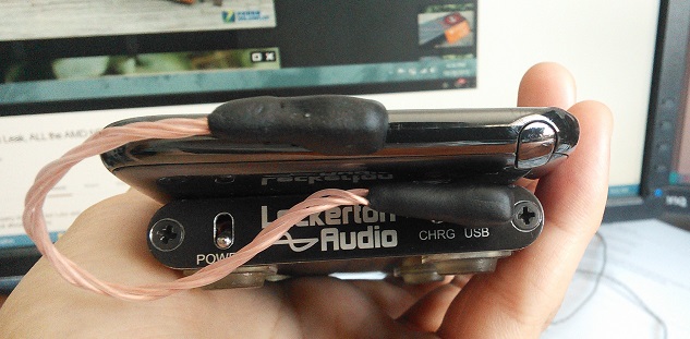
10. If everything tests ok on the multimeter, see if it works with your rig.
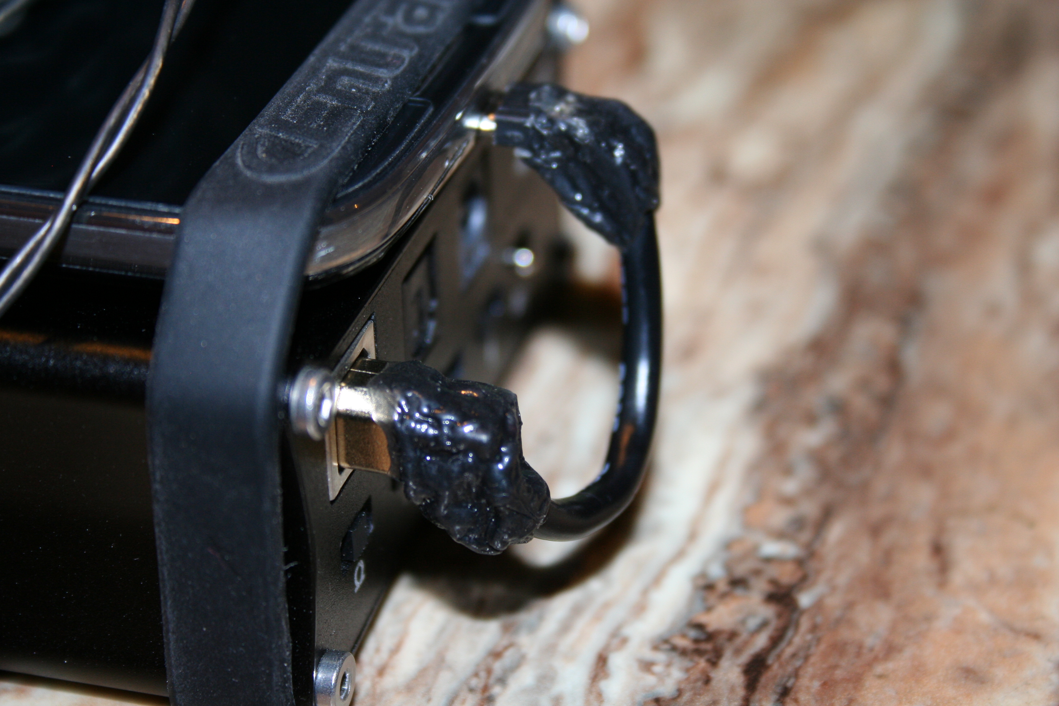
11. If everything works ok, finish the bodies of your connectors with something like epoxy putty or my favorite, Sugru. Hot glue could even work if you want something see through.
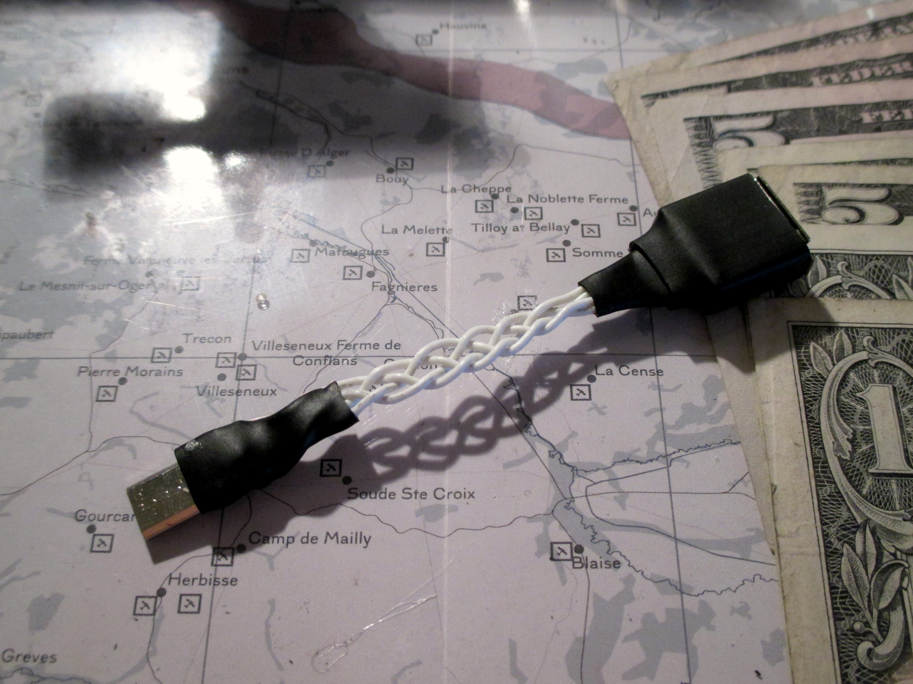
12. Done:


Have fun!
It turned out alright (confirmed to work with my Note II and my Nuforce HDP) so I decided to post this tutorial for anyone with an Android device that is USB OTG capable for use with outboard DACs.
Please forgive me for not having more pictures - I always forget to document things until I am half way through.
DISCLAIMER: This info is only for the connectors that I used. I am also human and might have mislabeled something. Always verify my info with what you know and find out about the connectors that you use.
1. Obtain Micro USB B connector. I got mine on ebay. While this listing isn't the one I bought (can't find the original), these look like they should work: http://www.ebay.com/itm/DIY-Micro-USB-Type-B-Male-5Pin-four-piece-assembly-Connector-black-color-10pcs-/160922939469?pt=US_Cell_Phone_PDA_Cables_Adapters&hash=item2577c1304d
2. Obtain USB B connector. I harvested mine from a monoprice cable (use heatgun to soften molded cover and remove with pliers and a cutter). You can get them at any electronics shop like Mouser or if you want a pretty gold plated one, Doublehelixcables had them at last check.
3. Link pin 4 and 5 on the Micro USB B connector. This short will let the Android device recognize the cable as an OTG cable and treat whatever is on the other end accordingly.
The picture above shows the pins (4 and 5 linked with a small jumper of wire) on the connector I used (not guaranteed to match, please check whatever documentation you get for your connector or check for continuity using a multimeter). The red arrows are pointing to the three pads on top, the blue indicates the that the other two pads are on the bottom. They alternate top and bottom.
Another shot showing the jumper and a better idea of where the bottom two pins are.
4. Carefully plan out the length of your wires, as there isn't a lot of room or margin for error. The pads for soldering are very close together so also be careful about how much solder you use and how thick a wire you use. You can see how 26awg fits from my pictures (might be as large as I would go).
5. I started the wiring from the USB B side since it easier to anchor and needed the most thought for placement of wire. I chose to have the wires come out of the top based on the layout of the M8.
Here is the USB B with the wires attached already at their respective spots. Again red indicates on top, blue on bottom.
6. Depending on the USB B connector that you get, you will have to cut down the shield to keep the cable as low profile as possible. I had some tin snips that I used to cut mine down to size.
7. At this point, you could braid your wires, but for me, for such a short cable with such small connecting points, I figured it would be more trouble than it is worth to do so. A simple twist should work fine.
8. Here is a picture showing everything wired up but with a couple labels added:
(sorry, didn't take a picture of the underside, but it should be straight forward at this point)
9. At this point, recheck pinouts and continuity to make sure you have the pins linked to the right pins on the other connector. Make sure there are shorts, as well.
10. If everything tests ok on the multimeter, see if it works with your rig.
11. If everything works ok, finish the bodies of your connectors with something like epoxy putty or my favorite, Sugru. Hot glue could even work if you want something see through.
12. Done:
Have fun!
![size]](http://files.head-fi.org/images/smilies/confused_face_2.gif[size=13px][/size])
![size]](http://files.head-fi.org/images/smilies/smile.gif[size=13px][/size])
![size]](http://files.head-fi.org/images/smilies/tongue.gif[size=13px][/size])
![size]](http://files.head-fi.org/images/smilies/cool.gif[size=13px][/size])
![size]](http://files.head-fi.org/images/smilies/beerchug.gif[size=13px][/size])
