Modding the Sony SCD-CE595
Jan 2, 2007 at 6:09 AM Post #31 of 93
Quote:

Originally Posted by colonelkernel8 /img/forum/go_quote.gif
I have a CDP-CE595, is it identical to this unit? I would love to upgrade it.


No it is not the same unit. The unit we are discussing is SCD-CE595.
 
Jan 2, 2007 at 8:46 PM Post #34 of 93
Sounds like you are making great progress! Can you share some pics of your handiwork?

Also, did you replace the stock opamps with opa627 or opa827?

Quote:

Originally Posted by johnmatrix /img/forum/go_quote.gif
I managed to replace the pos opa with 2 827s soldered to a browndog. I had to attach wires to the soic leads and then attach them to the adaptor in order to use the adaptor. The resulting sound is stunning and much cleaner than the player with all the caps replaced.

However, the gain as previously reported dropped very low. When I looked at the output, I had only 1.2 Vrms coming from the player. So I took a look at the schematic of the output stage and found resistor 411 and 409 also 511 and 509 formed voltage dividers, I jumped R411 and R511 to boost the output voltage. Jumping the resistors lowered the Vrms to 0.8, so I will go to rat shack tomorrow and see if they have some resistors. Hopefully this will let me change the opa and allow me to reraise the gain to get it to the proper voltage.


Jan 3, 2007 at 12:35 AM Post #35 of 93
I replaced the stock pos opa with 827s. I highly recommend bypassing or replacing the stock opa. I will post pictures of my 'handiwork' when I get home. It is definately rough; I lifted two opa leads and had to trace the circuit to find the next connection point. I would not recommend this player for complete newbies; I had had an electronics course and lab which helped me immensely.

When I replace R411 and R511 with higher voltage resistors, the output voltage increased! I boosted the output voltage to 1.7 Vrms with a 220 ohm resistor from 1.2 Vrms with 100 ohm. I left the player's output intentionally low because my headphone setup has such high gain. If you want the normal output(2 Vrms), make the resistors higher. Another alternative to raising the resistance at R411 and R511 is lowering it at R509 and R409. So it seems you can replace the opa, you will just have to change the voltage divider before the output to boost the output voltage.
 
Jan 5, 2007 at 2:09 AM Post #37 of 93
I have finally finished modding my CE595. In summary, I replaced all but the two 10 mF caps with elna cerafines and the two 10 mF caps with nichicon muse caps. I also replaced the opa with 827s which dramatically lowered the gain on the player. This was actually a desirable affect for my system as I moved from listening at 8 o'clock to 12 or 1 o'clock on my behringer. I also replaced R411 and R511 with larger value resistors to boost the gain. Replacing them boosted the output voltage however, I don't think the gain changed in the circuit. Overall changing the opa is not worth it. Just bypass and be done with it. There is a lot of hassle and it lowers the gain by a lot and unless you are good, a lead will be lifted. In my case, I ended up lifting 4, not in the desoldering process, but in trying to solder the new leads on. It was a pita to trace the circuit to find where to solder the leads and I could not have done that without the service manual.

The player post modification is a lot more laid back, the background is blacker, and there is more detail than before. My player is not burned in currently and I will listen to it some more to see how impressions change over time. I know the output caps supposedly take 100 hrs before they settle.
 
Jan 8, 2007 at 2:11 AM Post #38 of 93
Well I have some wonderful news, after all my mods to the analog section, the optics gave out. Initially, the player would stop in mid song and not play and now all I get is a table of contents error with no disk read. I have called Sony tech support and followed all their advice without any change in player. Does anyone have any suggestions? I can't send it back because of the mods to the player, so I think I am SOL right now.

I am currently using my denon 2900 for a dvd player. I am thinking that I may buy an oppo 970hd and re use the 2900 for my audio needs. Does anyone have any comments on oppo 970 vs 2900 as a dvd player?
 
Jan 18, 2007 at 8:53 PM Post #39 of 93
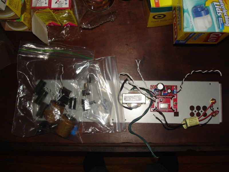
My second CE595 malfunctioned so I am offering all the parts for SOLD here.
DSC00823.jpg
 
Jan 29, 2007 at 3:21 PM Post #40 of 93
Guys and gals my second unit went to the Spare parts bin after it malfunctioned. I think it was the front channel DAC chip after an accident I had doing the Swenson mod.
frown.gif
It lived for about two hours and during that time I have to say that the replacement clock made a huge difference. If my aural memory serves me, the soundstage improved dramatically. If you go that route, be careful, the stock crystal is very difficult to desolder. I ripped off two PCB tracks doing it, but luckily was able to repair them with Crazy Glue and solder.
biggrin.gif


Also, if you are doing the Auricap Tweak, use Auricaps. They made a huge and I mean huge difference over the ClarityCaps in the same location. In fact, I removed the ClairtyCaps from my first unit and replace them with the Auricaps from the now dead second unit.

I am done with modding the SCD-CE595. If you have the skills and patience, modding the unit can reap great rewards, but to be honest, I do not believe this unit to be a very good candidate for modding. The numerous SMD components, the "tough" solder, and the cheap PCB are the major drawbacks that can leave a DIY'r frustrated and with a non-functioning unit.
 
Jan 26, 2008 at 2:27 PM Post #41 of 93
So the auricap and swenson mods are do able for a beginner? I have a steady hand and a jewler's mangifier headset. It looks as if it is worth a try?
Thanks for the great thread, it is very interesting to see how these machines work.
 
Jan 26, 2008 at 4:17 PM Post #42 of 93
With some time and patience, probably. I did these mods for a friend of mine, and like everyone else says, it makes a very nice difference. You have to realize all of these closeup pictures make everything look bigger than it really is. I can guarantee the part you will have problems with is doing the swenson mod and soldering the caps to IC200. I found it worked best to install your new jacks on the chassis and attach the caps to them. Then get the caps in pretty much the spot they are going to wind up before you solder them. Otherwise there is just so little physical contact when you solder it, they break off very easily if the caps move. Also, I found the best way to get a nice lead to solder onto the IC200 is to take a resistor lead and solder it to the cap wire. I should get pictures of the one I did, I thought it turned out very well.

I would also have your Hot-Glue gun ready, I felt a lot better after throwing a blob of glue on the IC200/cap connection after I verified everything was working 100%.
 
Jan 27, 2008 at 5:36 AM Post #43 of 93
A picture would be a great help thank you for the technical advise hot melt is great stuff.
 
Jan 27, 2008 at 6:25 AM Post #44 of 93
As someone who modded the unit, the best advice I can give you is buy ChipQik SMD desolder. It is an alloy that lowers the melting temp of the solder when it is melted with the solder on the board. It makes nightmare SMD desoldering a breeze. I did not use it on this unit, but I used it on my denon 2900 to great effect.
 
Jan 29, 2008 at 1:52 AM Post #45 of 93
Thanks that looks like a great product, I just ordered it. I will also attach a solid wire lead to the stranded wires from the Auricaps. It make sense. I will let you know how it goes.

Does anyone have any experience with the Mundorf caps? They have some very expensive caps and I don't know enough about them. My guess is the Auricaps are fine. The Mundorfs are 2-4 x the $. Teutonic magic?

Now if I decide to dive in further, replacing he op amps with Burr-Browns would be the next step? (not to get ahead of myself or anything).
Thanks again for all of the advice.
John
 

Users who are viewing this thread

Back
Top