Schiit Mjolnir 2 Listening Impressions
May 26, 2024 at 3:43 AM Post #6,961 of 6,963
Might we see some pics?

I have been investigating ideal bridges, did you do all voltage rails or only certain ones? Considering the CRC network directly after the bridge rectifiers, did you up the resistance to account for extra volts not wasted by the ideal bridges. Very curious to know your results and methodology!
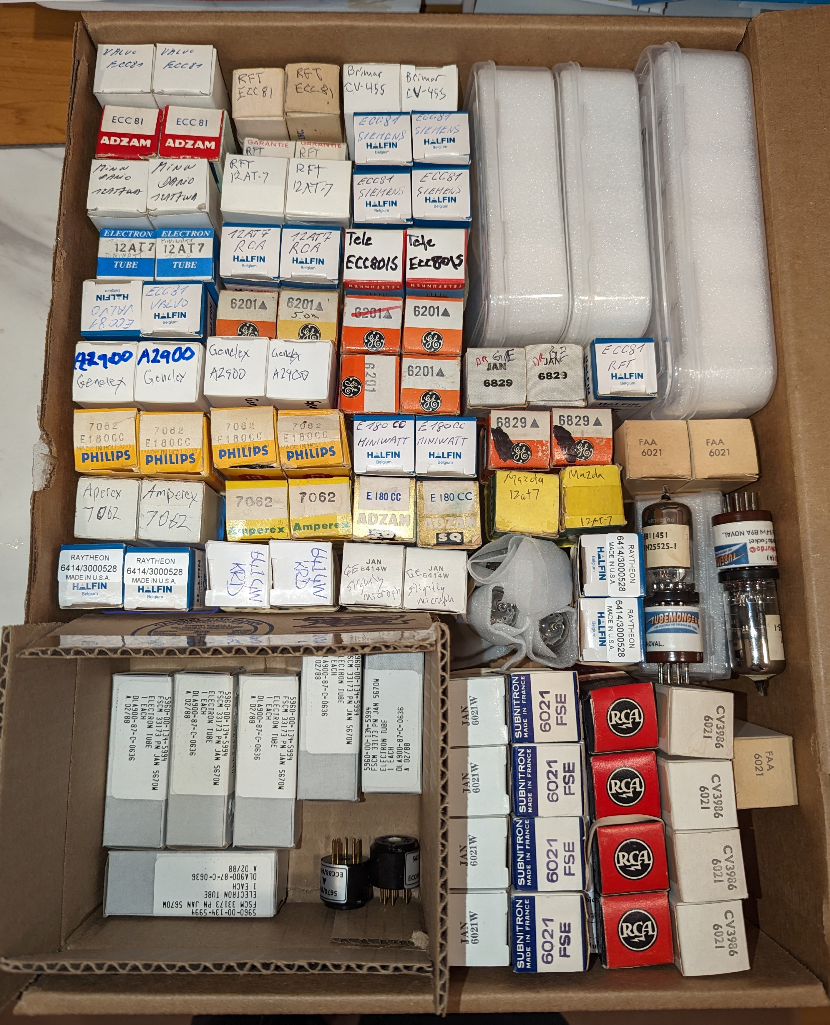
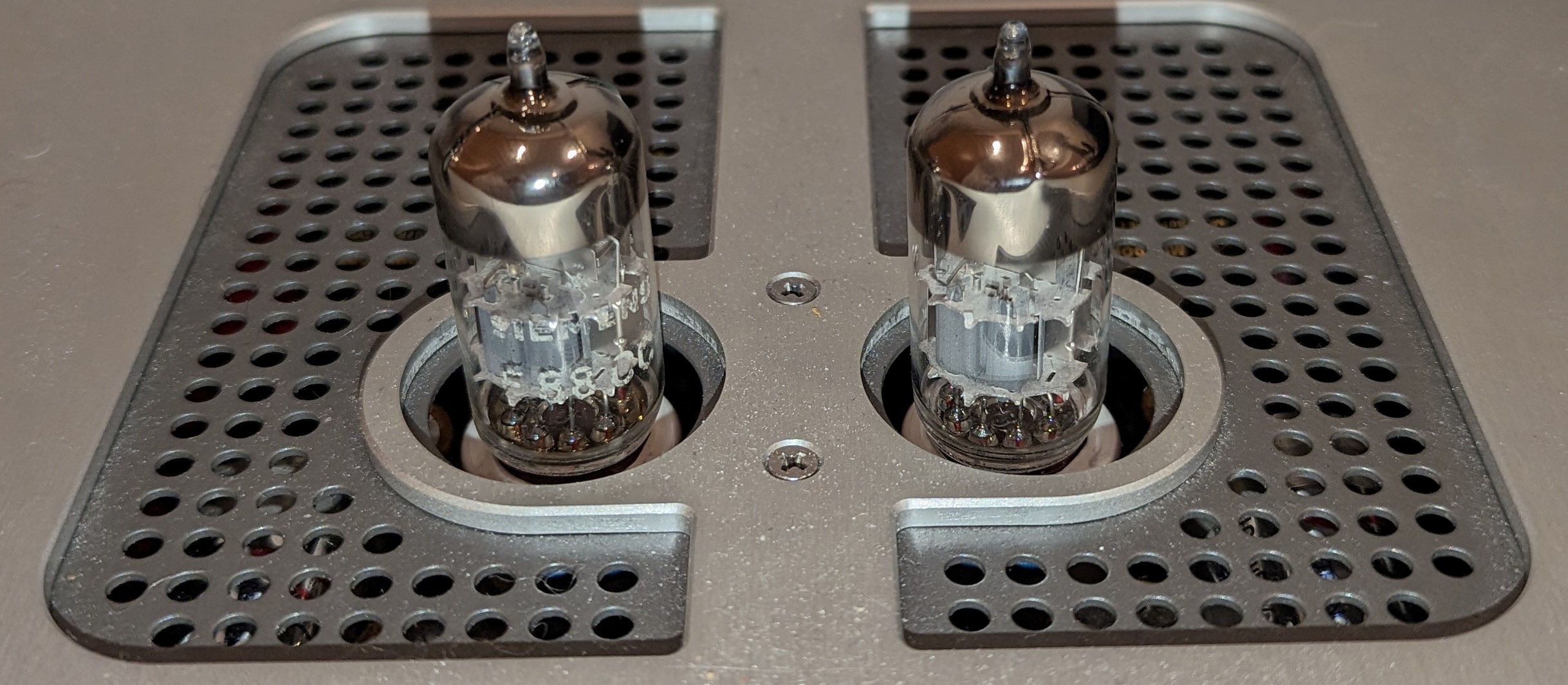
Over a year I'm running ideal bridge 1-side temporary board in heating circuit because of obvious benefits. In meantime I made final version of ideal bridge to implement across other low voltage rails but still delaying this and thinking of other combined updates.
Some pictures.
Mj2_p2.png

Mj2_top.png

MJ2_IB.png
 
May 26, 2024 at 4:44 AM Post #6,962 of 6,963
Very Cool, Gumisb! Thanks for the response!

I Like the compact size of the ideal bridge. What were the benefits for the heaters?

What did you end up with for coupling caps? What are those caps between the 1000uF elecrtrolytics (amber color)? Are those white MKP caps by the heater regulators in parallel with the 2200uF ones? I'm sorry, just very curious!
 
May 26, 2024 at 6:28 AM Post #6,963 of 6,963
Input voltage for regulator is up to 16V so additional 1.4V from ideal bridge instead dissipated as heat in diode can be used by regulator and tubes. Less high frequency noise coming from diode switching, less load on transformer. Cooler amp.
All caps are PP film miflex. Some are in Kapton tape so that's why they look amber. Decoupling are 0.1uF for regulators too.
 

Users who are viewing this thread

Back
Top