


tangent
Top Mall-Fi poster. The T in META42.
Formerly with Tangentsoft Parts Store
- Joined
- Sep 27, 2001
- Posts
- 5,970
- Likes
- 58
I've been thinking about low battery indicator circuits lately.
So far, the only thing I've seen on these forums is ppl's zener/CRD circuit, used in his personal amps and then adopted into the PPA and PIMETA. Just shutting the LED off when the battery is low is kind of weak, though: it isn't an indication, it's a lack of indication. You can infer that the battery is low, or you can infer that there is no power at all.
Last night I came up with this circuit:
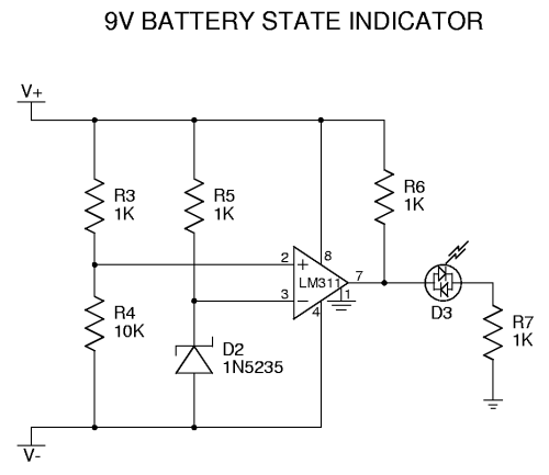
It uses a bicolor LED (just two matched LEDs wired back-to-back) set to show green when the supply is over a certain voltage, and red when it drops under that voltage. The comparator (LM311) might oscillate when the midpoint of the voltage divider is right at the zener voltage, in which case you'll get orange or yellow, depending on the LED. There's a low-power version of the comparator (LP311) that would be ideal here; you could probably tune it so the entire circuit draws maybe 2mA more than the LED alone.
Bicolor LEDs are available in all possible combinations of red, yellow and green. Sadly, there are no bicolor blue+X or white+X LEDs yet, probably because the voltage drops are too dissimilar, so matching the two chips for brightness would be a problem.
You could easily modify the comparator circuit to just turn on a low-battery LED, and have a separate power LED. This would open up the full range of LEDs to you, since it doesn't depend on a bicolor type.
Another variation I've seen runs the LED normally while the supply voltage is high, but flashes the LED when it gets low. This one uses just a single LED, but it does need more active parts than any of the above circuits.
A zener plus a CRD is about $2, so all of the above circuits actually are about the same price or cheaper. They all take more board space, so there's little choice in a compact circuit like the PIMETA. But if space isn't an issue, which would you rather have? Are there any other cool low-battery circuits you've seen that you like better?
So far, the only thing I've seen on these forums is ppl's zener/CRD circuit, used in his personal amps and then adopted into the PPA and PIMETA. Just shutting the LED off when the battery is low is kind of weak, though: it isn't an indication, it's a lack of indication. You can infer that the battery is low, or you can infer that there is no power at all.
Last night I came up with this circuit:
It uses a bicolor LED (just two matched LEDs wired back-to-back) set to show green when the supply is over a certain voltage, and red when it drops under that voltage. The comparator (LM311) might oscillate when the midpoint of the voltage divider is right at the zener voltage, in which case you'll get orange or yellow, depending on the LED. There's a low-power version of the comparator (LP311) that would be ideal here; you could probably tune it so the entire circuit draws maybe 2mA more than the LED alone.
Bicolor LEDs are available in all possible combinations of red, yellow and green. Sadly, there are no bicolor blue+X or white+X LEDs yet, probably because the voltage drops are too dissimilar, so matching the two chips for brightness would be a problem.
You could easily modify the comparator circuit to just turn on a low-battery LED, and have a separate power LED. This would open up the full range of LEDs to you, since it doesn't depend on a bicolor type.
Another variation I've seen runs the LED normally while the supply voltage is high, but flashes the LED when it gets low. This one uses just a single LED, but it does need more active parts than any of the above circuits.
A zener plus a CRD is about $2, so all of the above circuits actually are about the same price or cheaper. They all take more board space, so there's little choice in a compact circuit like the PIMETA. But if space isn't an issue, which would you rather have? Are there any other cool low-battery circuits you've seen that you like better?


