The Dynahi Construction Related Questions Thread
Aug 18, 2004 at 8:23 PM Thread Starter Post #1 of 630

rsaavedra

Headphoneus Supremus
Joined
Jan 20, 2002
Posts
5,819
Likes
21
I thought would be a good idea to start a thread that will compile all or most Dynahi construction related questions. There are and will be many such questions along the way. Some people are posting some already in the Elma Attenuator Groupbuy Thread, and some others are posting questions in the Dynahi Boards Groupbuy Thread.

I have one question myself. Related to populating the Elma attenuator. How do I know what's best for me, whether a 25k vs 50k configuration??? Is that more or less equivalent to fixing the attenuator to a Hi-gain (25k) vs a Low-gain (50k)?
 
Aug 19, 2004 at 1:22 AM Post #3 of 630
On the fets you don't connect the middle pin, either bend it up
or cut it off.
 
Aug 19, 2004 at 1:24 AM Post #4 of 630
Post some pr0n when you can, guys.
wink.gif


-Ed
 
Aug 24, 2004 at 1:07 AM Post #7 of 630
Trevor, the op-amp I'm going to try out first for this amp is the OP177GP, which someone had mentioned in a previous thread.

Just to be thorough, I'm going to repost my board propagation quasi-guide in this thread (I had posted it in the Dynahi pics board earlier today)...


1093076610580_board1.JPG


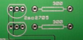
On the right in this picture on top and bottom are spaces for resistors -- these can be recognized by the long rectangular shapes with leads coming out each end. Resistor orientation isn't really specific, but for continuity you should orient it so that the letters on the board and resistor are going in the same direction. Pull the leads in from each side of the resistor so that it is close to the board itself.

To the left on top and bottom are transistor slots -- the transistors themselves have three leads that all eventually bend inward. You want to push the leads through until you reach those bends. You should feel resistance when you get there. Orient the transistor so that the curved side lines up with the curved image on the board.

1091905750276_board2.JPG


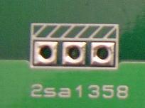
Here we have a transistor slot with a heat sink attached, as shown in the image. Again, line the heat sink (the silver part of this type of transistor) up as it is shown on the board.

1095241751780_board3.JPG


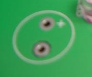
Here you can see a slot for a capacitor -- note the + next to one of the holes. This indicates that the capacitor is a polarised one, and the positive lead goes in the plus side. You should be able to identify the positive lead because it should be longer than the negative lead.

1093093211733_board4.JPG


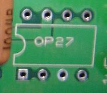
Here is an image of the op-amp slot on the board. Again, the indent seen on the left side of the op amp should line up with the indent (or sometimes simply a mark or small hole) on the op-amp. You might want to first install a socket for the op amp so that you can easily replace it if it goes dead or you want to do some op-rolling. ^_^

1092145214605_board5.JPG


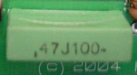
This is a picture of the rectangular capacitor that's near the bottom towards the middle-left of the board. This is a non-polarised capacitor, but you may as well orient it so that the text on the cap sits the same way as the text on the board.
 
Aug 24, 2004 at 4:02 PM Post #8 of 630
I haven't gotten the transistors yet and was wondering if the package on the 2SC3421 and 2SA1358 is all plastic or metal backed? Will they need to be electrically isolated from the heatsink?
 
Aug 24, 2004 at 4:14 PM Post #9 of 630
if i remember from my brief look at the transistors i have, they are all plastic, although i seem to remember kevin saying that silicon washers are needed to insulate them from their mounting screws. i could be wrong, though.
i am also wondering about the heatsink group buy. kevin posted what heatsinks he used and said they were relatively cheap if purchased in bulk. i would imagine that somebody could start to organize the group buy relatively soon. i would volunteer, but i am too busy with school and i am afraid i dont have the patience or resources that raul does. if someone searches through one of the threads related to the dynahi, they can find a link to the heatsinks.

peace
dan
 
Aug 24, 2004 at 8:47 PM Post #12 of 630
The HS-TWS will work fine. In fact i just ordered a dozen.
Much easier than the $72 i paid for the first 2.

The silicon wafers are to make sure there is real good contact
between the transistors and the heatsink. No electrical isolation
is needed.

I'm getting too old to deal with messy thermal glue. Peel and stick.
mouser part number 532-53-77-9ac
 
Aug 24, 2004 at 9:54 PM Post #14 of 630
1 heatsink per audio channel. Plus an angled piece of aluminum cut
to shape and punched or drilled per channel.

You could use a 3rd heatsink for the pass transistors for the
(yet to be designed) power supply.

There just aren't enough hours in the day...
 

Users who are viewing this thread

Back
Top