00940
Headphoneus Supremus
- Joined
- Nov 6, 2002
- Posts
- 4,493
- Likes
- 47
There are of course plenty of commercial dac-amp combo on the market right now, many of these powered by USB. Some are even quite cheap and decent. But since DIY isn't about saving money but about having fun, I'm starting to gather ideas to build my own.
The aim would be to have a smallish box I could take away on vacation and the like (not really a portable amp thus) and which would be able to power HD650 (300r) and HD25-13 (600r) somewhat properly. I don't want batteries nor a power supply. Just usb in, headphones out.
Soooo:
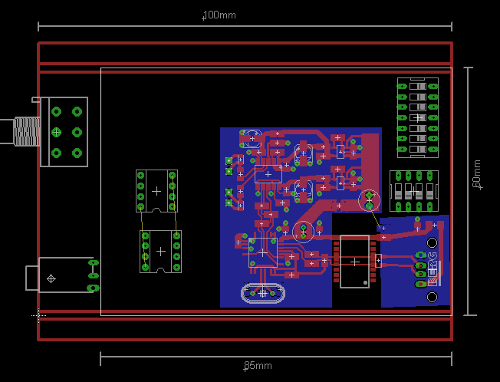
- Case: the aim is to fit everything into a galaxy GX147 (124*170*40mm).
- Power supply: the digital boards required 5V, with regs onboard to take it down to 3.3V. I'll probably simply run the USB power through a lclc filter. For the amp section, a DC-DC converter is pretty much mandatory. Probably the NMH0509DC from Murata, followed again by LC filters. The datasheet promises 5mVp-p ripple with an additional filter. +/-9V rails should be ok for the hd650.
- USB receiver: if one wants to build his own board, only the pcm270* serie is easy to buy as parts in small quantities. Otoh, there's a lot of built boards for sale with xmos, te7022, cm6631a or sa9023. A bit less diy but those offer support for 24bits and higher sample rates than the good old TI parts. For now, I'm considering this board. The SA9023 doesn't require extra drivers and this particular pcb provides pads for a 5V external supply while having a ldo onboard. I'll remove the spdif section to save a tiny bit of power.
- DAC: the es9023 has the great advantage to be able to run in async with its own master clock, reducing the reliance on the quality of the incoming I2S lines. Problem once again is that the es9023 isn't easy to buy in small quantities... built board time again. This one looks half decent for this application. A local clock is onboard. I'll have to unsolder those big rca.
- Volume control: hesitating... in theory, with 24bits support, I should be able to control the volume from the computer, in the digital realm. But, from experience, it's easier to make mistakes with a digital volume control and a good old pot is safer. I might use a blue velvet in there.
- Amp: I was considering the tpa6120a2 in multiloop.. but current draw is a bit high at iddle and I don't really need its current abilities for my high impedance cans. I'm thinking about using a njm4556 inside a opa2134 loop. Why the opa2134 ? To interface the amp inputs easily with an analog potentiometer (jfet inputs...) and so that I can put RC filters in the opa134 power lines, to increase the power supply ripple rejection of the whole amp. Something like this:

What do you guys think ? Something I overlook, something you would do differently ?
The aim would be to have a smallish box I could take away on vacation and the like (not really a portable amp thus) and which would be able to power HD650 (300r) and HD25-13 (600r) somewhat properly. I don't want batteries nor a power supply. Just usb in, headphones out.
Soooo:
- Case: the aim is to fit everything into a galaxy GX147 (124*170*40mm).
- Power supply: the digital boards required 5V, with regs onboard to take it down to 3.3V. I'll probably simply run the USB power through a lclc filter. For the amp section, a DC-DC converter is pretty much mandatory. Probably the NMH0509DC from Murata, followed again by LC filters. The datasheet promises 5mVp-p ripple with an additional filter. +/-9V rails should be ok for the hd650.
- USB receiver: if one wants to build his own board, only the pcm270* serie is easy to buy as parts in small quantities. Otoh, there's a lot of built boards for sale with xmos, te7022, cm6631a or sa9023. A bit less diy but those offer support for 24bits and higher sample rates than the good old TI parts. For now, I'm considering this board. The SA9023 doesn't require extra drivers and this particular pcb provides pads for a 5V external supply while having a ldo onboard. I'll remove the spdif section to save a tiny bit of power.
- DAC: the es9023 has the great advantage to be able to run in async with its own master clock, reducing the reliance on the quality of the incoming I2S lines. Problem once again is that the es9023 isn't easy to buy in small quantities... built board time again. This one looks half decent for this application. A local clock is onboard. I'll have to unsolder those big rca.
- Volume control: hesitating... in theory, with 24bits support, I should be able to control the volume from the computer, in the digital realm. But, from experience, it's easier to make mistakes with a digital volume control and a good old pot is safer. I might use a blue velvet in there.
- Amp: I was considering the tpa6120a2 in multiloop.. but current draw is a bit high at iddle and I don't really need its current abilities for my high impedance cans. I'm thinking about using a njm4556 inside a opa2134 loop. Why the opa2134 ? To interface the amp inputs easily with an analog potentiometer (jfet inputs...) and so that I can put RC filters in the opa134 power lines, to increase the power supply ripple rejection of the whole amp. Something like this:
What do you guys think ? Something I overlook, something you would do differently ?


