Electrostatic hybrid amp discussion thread
Jan 26, 2014 at 8:53 PM Thread Starter Post #1 of 15

00940

Headphoneus Supremus
Joined
Nov 6, 2002
Posts
4,493
Likes
47
Since I don't want to go further OT in Wakibaki's thread, I thought I'd create a new thread to post this. To be completely honest it is very much an intellectual exercise for now. So I'd really welcome anyone's input. Even to tell me this is completely wrong and i've been tricked by ltspice.
 
The following amp has very little in common in terms of topology with the ones posted earlier. In particular, it doesn't use the opamp to automatically bias the tubes anymore. Still, it is not very original and was thought off after reading many suggestions by Broskie, Gilmore, JCX, Spritzer, Wakibaki (and probably others I forget). 
 
So here is the current suggestion:


The output DC-level is actually set to near 0V by the gnd-referenced mosfets on top, set up as µ-followers. Since the top mosfets have a fixed dc reference, we can maybe replace the suggested depletion mosfet by common ones. A quick search through digikey's filters brought me to the FQD1N80 (and maybe STD1NK80Z).
 
The tubes provide most of the voltage gain, the mosfet take care of most of the current variation. In sims, full output (about 1000Vp-p) at 20khz into a 130pF load is achieved, with a biasing of about 7ma per side.
 
Obviously, the input requires a balanced input. An alternative gain stage could replace the two opamps.
 
One thing that bugs me is that the output stage runs without global feedback, at the contrary of the schematic here . Still, lightly loaded triodes are fairly linear.
 
For the power supply, I would use Elvee's excellent "simple hv regs."  I've got one working flawlessly at 300V for a µ-follower hybrid.
 
Jan 27, 2014 at 7:35 PM Post #2 of 15
Neat design! The op amp gain stage probably makes it super inexpensive to build and still have reasonable distortion, but I haven't seen them used in Stax amps outside of servos before. Make sure that it's up to driving the tube you use.
 
The 6SN7 isn't a great choice here. It has a max plate voltage of 250V, which the amp will happily exceed. EL34 triodes or 6S4As seem to be the go-to output triodes because of their high Va-max, but there are lots of neat Russian tubes and TV pentodes that would be up to the task too.
 
If it were me I'd consider replacing R7 with a current source. If you reduced the rails to +-250V you could use a DN2540 cascode and still have a nice little amp. Power supply parts would probably be considerably cheaper too.
 
Also consider bypassing R8/9 with a capacitor to restore some gain, if you don't do the current source. It'll increase the gain quite a bit, and maybe allow for some NFB.
 
Jan 27, 2014 at 8:28 PM Post #3 of 15
Thanks for the comments.  :)
 
- About the opamps: yes, depending on the tubes, one might want to use the OPA2604, as they can stand higher rails (+/-24v) and thus swing quite a bit more.
 
- The common 6sn7 wouldn't like it indeed. But 6sn7-gta are supposed to accept a plate voltage of 450V so would be ok. I see quite a few on ebay at reasonable prices.
 
- Good call on R7. It really doesn't see much voltage variation, we could use parts rated for low voltage there. Maybe with a 15V zener clamp for fault conditions and startup ?
 
- I don't have much experience with electrostatic phones requirements. Is there much to be lost going from +/-300 to +/-250 ? That would also reduce the dissipation on the FQD1N80 which are smd devices (cheap ones too, if they're suitable, at 0.8$).
 
Jan 27, 2014 at 9:23 PM Post #4 of 15
Why not an asymmetrical B+/B- supply? +270V/-320V sounds reasonable. 
 
I'm not such a fan of the Mu-follower here. Stax headphones always seem happiest driven from a high output impedance source so this seems like a great place to save some complexity. 
 
You might like the 5687 as an output tube. 
 
Jan 27, 2014 at 11:03 PM Post #5 of 15
A couple of little things....
 
7mA per side? That's a lot of current for a human. I'd be happier with a couple of capacitors between me and that much current @ 300V in the event of a fault condition. This is not the same as the bias voltage, which can be constrained to be of the order of a few hundreds of microamps max. I know there is a strong pull to keep things DC coupled, but the circuit is AC coupled already, and the load is in the megohms, you don't need an electrolytic. Don't forget that you need a bias supply of ~600V or more, a single rail lessens the complications here, you haven't really gained much by going dual-rail.
 
There are signal voltages developed across R3, R4 being amplified by the FETs. Those signals are produced (distorted) by the tubes below without the benefit of GNFB. I haven't simulated the circuit, but I don't think the arrangement bodes well for the overall distortion.
 
The 6SN7GT has a peak plate pulse voltage of 1500V under some conditions, Broskie is operating his with a B+ of 700V. You'll probably be OK there. Since the peak is the quiescent + the swing, you can limit the peak by limiting the drive, at least in a prototype.
 
A regulated supply is probably superfluous given the topology's potential for PSRR, depending on the exact arrangement. Looking at the general availability of encapsulated PCB mount transformers to run back-to-back as opposed to tube power transformers, if you can keep the current to 20mA total instead of 28 then you stand a better chance of keeping the whole thing reasonably compact and cheap. Of course I have the advantage of 240V mains supply.
 
I'm going to build an all-MOSFET one first, the FR is flat out to 100k into 120pF @ 5mA per side (240pF total), I have the MOSFETs already. 
 
I see Digikey in the US have DN2470s (700V) in TO252.
 
Jan 28, 2014 at 5:18 AM Post #6 of 15
Thank you for the critical questions, that's what helps most.
 
- The ac/dc coupled thing. Considering my aim was to design a "cheap" version, capacitor sound (or the absence of it) isn't the main drive. I was more concerned by comments by more than one builder on the difficulty to find suitable capacitors that don't "sing" at such crazy voltage swings (Gilmore, Broskie too iirc).  I've to research more stuff about that.The drive to bipolar supply is linked but a bit different. It allows cheaper parts to be used, reduces the building risks and the insulation problems, etc. The bias will indeed require a voltage doubler but since there's no current draw to speak of, that's ok.
 
Btw, the standing current has little to do with how much current could run through you in case of a fault since there are no big resistors in between the output and the 300V rail. That would reinforce your point about safety...
 
- R3-R4 significantly decreases distortion by presenting a higher load to the tube and making it operates at a more constant current, the higher the value the better actually. That reduces voltage swings obviously, so a compromise has to be found. The classical piece by Alan Kimmel on µ-followers is a good read.
 
- Good call on the back to back transformers. This said, a CT 250-0-250 classical tube transformer could well be cheaper. Cheap is more important than compact to me. I've got to check.
 
- Now, I just can't see how the power FR could be flat to 100k with 5ma per side. Small signal maybe. At full swing at 100K with +/250V rails, you need +/30ma for a 130pF load. +/-6.5ma for 20k. There's also a mistake in your sims: capacitance in serie is halved, not doubled. So if you simulate open ended, you need to sim into 240pF per side, not 120pF. This being said, you're right, current is excessive, 20K at full amplitude is not a common signal in audio. If we aim for a power bandwidth of 10K, we can easily reduce the standing current to 5ma per side while keeping the whole comfortably biased in class A.
 
As a side note, I've found an existing µ-follower amp (all tube though): http://www.dddac.de/tp08.htm . He's running at 400V supply and 4X15ma (which seems quite an overkill considering his limited voltage swing)
 
Jan 28, 2014 at 2:46 PM Post #7 of 15
  As a side note, I've found an existing µ-follower amp (all tube though): http://www.dddac.de/tp08.htm . He's running at 400V supply and 4X15ma (which seems quite an overkill considering his limited voltage swing)

 
I'm pretty sure that he feeds the amp from a standalone preamp, so voltage swing may not be as limited as you think. I have often wondered why so few DIYers do that - build a preamp (or a more conventional dynamic headphone amp in the style of a preamp), and use it to run an electrostatic output stage. Or use an OMFGWTFPower!!!! buffer after a more conventional preamp to drive dynamic headphones, but whatever. 
 
It is also worth note that this amp has the outputs a couple hundred volts above ground.
 
Jan 28, 2014 at 4:31 PM Post #8 of 15
   
I'm pretty sure that he feeds the amp from a standalone preamp, so voltage swing may not be as limited as you think. I have often wondered why so few DIYers do that - build a preamp (or a more conventional dynamic headphone amp in the style of a preamp), and use it to run an electrostatic output stage. Or use an OMFGWTFPower!!!! buffer after a more conventional preamp to drive dynamic headphones, but whatever. 

 
I was a bit unclear. What I meant is: the rail of his electrostatic amp are rather limited -19/415. So even with a strong preamp, he can swing about 700Vp-p at best. He doesn't need 30ma per channel for that, even at 20khz. The operation point was probably selected to be in the tubes sweet spot I guess.
 
 
  It is also worth note that this amp has the outputs a couple hundred volts above ground.

 
A bit scary, eh ?
 
Jan 28, 2014 at 5:52 PM Post #9 of 15
internal DC blocking/signal coupling or even output caps don't have large Vswing - trivial to be 100x lower Z than diff input Z or ES load C so Vac across the output C only moves <1% of output Vswing
 
the large polarizing DC V can be a challenge at least 2 ways
 
continuous Vdc rating has to be looked for carefully - often much smaller than expected from "withstand" or "tested" V which are short term
 
and hi DC V does cause polarization dependent electrostriction - so vibration coupling would be possible, and the (small) AC V could cause "singing"/tiny amount of distortion
 
since this effect is caused by the plates moving under the electric field's force it is bigger for film caps with poor windings, airgaps, soft materials
 
higher mechanical strength film, supporting higher mechanical winding tension is good, especially avoid oval "squashed" removable core types
 
 
NPO/COG MLCC are not piezoelectric, and being monolithic fired ceramics the plates don't move, and they can have very low distortion, DA - competitive with better films
 
I don't know if any measurement exits for the signal conditions of ES output C - but they certainly look to be in the running for having inaudible nonlinear/nonideal effects
of course they do cost more than many polypropylene, or even some polystyrene dielectric C for similar ratings and may have to be series/paralled for higher Vsupply ES amps
 
Jan 28, 2014 at 5:58 PM Post #10 of 15
   
I was a bit unclear. What I meant is: the rail of his electrostatic amp are rather limited -19/415. So even with a strong preamp, he can swing about 700Vp-p at best. He doesn't need 30ma per channel for that, even at 20khz. The operation point was probably selected to be in the tubes sweet spot I guess.


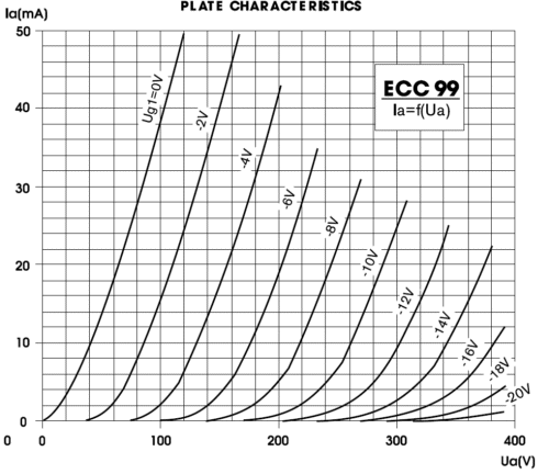
I would also bet that 15mA was selected to get the tubes into some sweet spot. 
 
225V/15mA with CCS's all around the tubes does indeed look quite linear.
 
 
JJ%20ECC99%20Plate%20Curves.png
 
 
Jan 28, 2014 at 6:07 PM Post #11 of 15
large voltage swings without feedback on a 6sn7 are going to be in the 2 to 3 percent thd range.
you really need feedback. other power tubes are going to be similar.

the output stage really does need to be dc coupled with a bipolar power supply. as simple
as fixed bas, but better with a ground referenced servo and a high voltage pnp transistor
similar to my old bamaslama design. then capacitor grid drive from an opamp with feedback
 
Jan 28, 2014 at 6:44 PM Post #13 of 15
this
http://gilmore.chem.northwestern.edu/bamaslama.jpg

but you have to change to driving the grid of the bottom of the tube.


this is the idea, then you wrap the gain with feedback around this

http://gilmore.chem.northwestern.edu/idea1.pdf

what you do is pick R2 for the tube and mosfet current you want
such that the output voltage is about +25 volts, then the servo will
take it down to zero and keep it there. C1 allows the output tube
to keep gain to max.

ksa1156 is a 400v part, so you can go up to +/-400v.
 
Jan 28, 2014 at 9:22 PM Post #14 of 15
Ok, time to go to sleep for me.
 
I'm a bit hesitant on the ac coupling thing. Mostly because of worries about one mosfet one day going short. Btw, speaking of mosfet, any input on the FQD1N80 suitability ?
 
The servo is nice but I wonder how necessary it is. I know it adds one cap but the µ-follower nicely set the bias very near 0 by itself. It also would be easier to servo (return the servo output to bias the mosfet, the tube will find his own operating point).


But of course, the servo would be needed for an overall feedback with an opamp. Feedback which is not that trivial I've discovered
mad.gif
  I'm more and more tempted by a 12ax7 gain stage.
 
Jan 30, 2014 at 1:20 PM Post #15 of 15
Ok. This is a bit more stimulating (challenging) to think about than most dynamic designs. I've been reading again what was posted here and on other forums (diyaudio, others).
 
A short summary of issues. Please excuse this rambling, writing it down helps clarify things to me
 
* Feedback:
 
Even if triodes are probably the most linear devices for large voltage swings, feedback is required. Short of designed a whole discrete input stage with HV parts, I've been looking at two options, tubes and opamps.
 
With opamps, Sennheiser (hev70) and Audiovalve (RKV) use the same technique of putting an inverting gain stage inside a feedback loop and also setting the output voltage point by biasing the opamp input. The advantage is that you can get all the gain you want from an opamp and a tube. It works fine but compensation is touchy (especially with triodes with varying µ). They got away with it by using tl071 and lf351, slow opamps. Playing with the ne5534's compensation pins could be an option. You also need an output cap since the output is sitting at HV. Attempts to servo the amp are quickly getting complicated (multiple PS, etc).
 
With tubes, the addition of a tube allows local feedback. Distortion isn't as vanishingly low as the opamp. But stability sims are much better. But you'd also need a gain stage in front of it to preserve enough gain for feedback.
 
* AC or DC-coupled
 
If DC coupled, the outputs near to be near gnd. And have to be kept there. Can be done with a servo. Could also be done with a gyrator.
 
If AC-coupled, suitable caps have to be found. The TDK FK serie of C0G caps isn't looking too bad. A 22nF/630V is 1.7$ at digikey (for use in parallel and series). TDK has plenty more at HV, but smd.
 
* Output device/topology
 
Mosfet have the advantage of lending themselves to tube topologies, simplifying things quite a bit, even if they often are a bit inferior to bjt wrt capacitance issue.
 
I'm pretty set on the µ-follower for the output if dc-coupled. It improves the tube linearity by running them at near constant current, provides twice the current into the load for same standing current and set the output voltage. It could also allow the use of common fets instead of depletion mode ones. The FQD1N80 is only 0.8$ at digikey with Ciss and Coss figures similar to the IXYS parts. Lowish dissipation ratings though.
 
Pseudo-srpp doesn't look to bad if the output voltage point must be set by a servo/opamp.
 
All this leads to the two following options; the first one uses a local feedback for the output stage lifted from Kevin Gilmore's all triode ac-coupled amp. The second is based on a hev70. These schematics are for illustration only, many safety parts missing, many parts values non optimal.


Users who are viewing this thread

Back
Top