The Stax SRM-002 mod thread
Jun 23, 2015 at 1:33 AM Post #31 of 53
the power supply section in 002 is different from the 001.
 
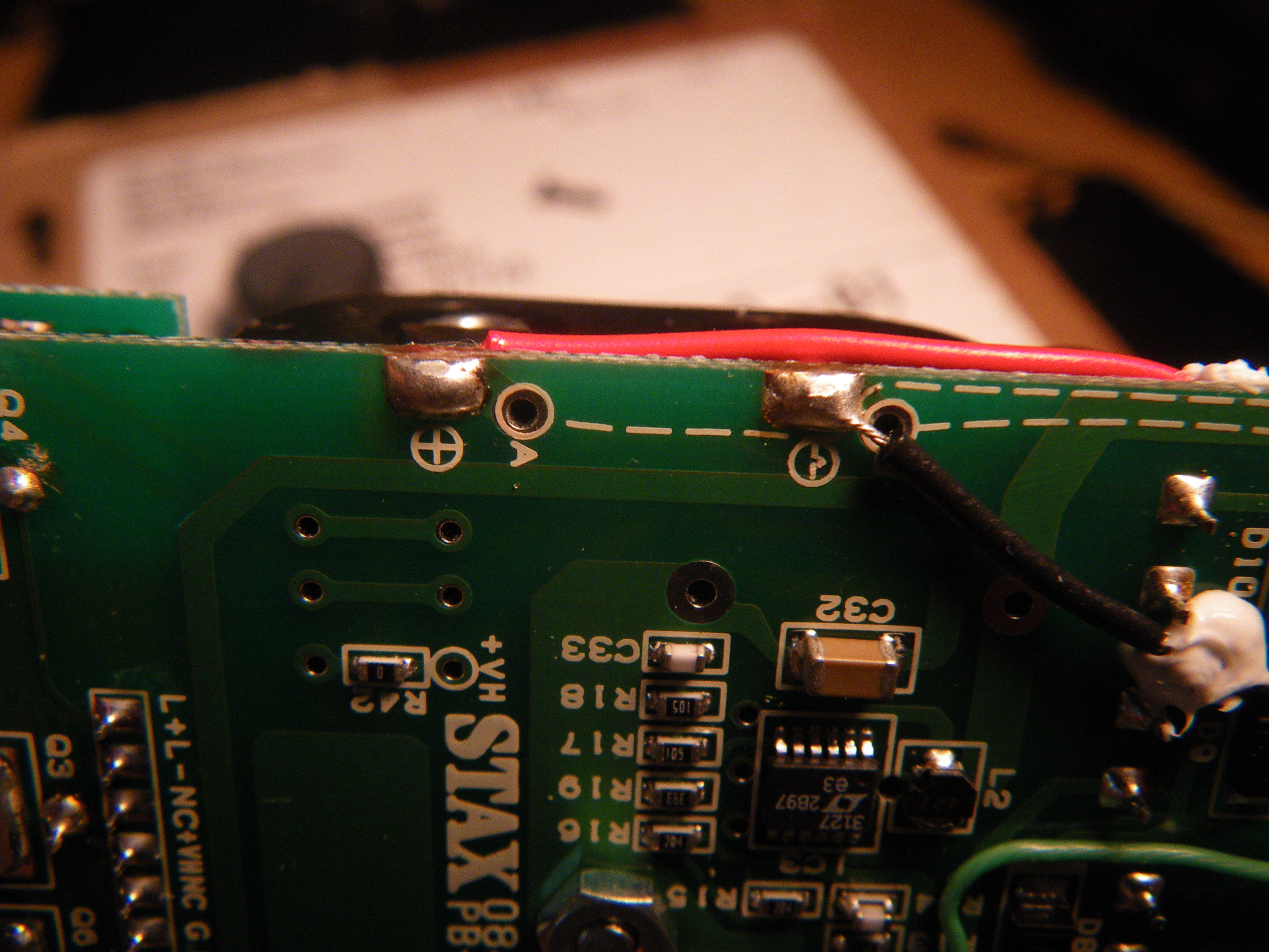
regulator for incoming power: 001 has a linear voltage regulator to drop the incoming voltage to around 2.8V, if the input is much higher than it will generate heat to burn off excessive input power (Q15 gets hot).  In the 002 the voltage regulation is done by a switch mode buck/boost chip, LTC3127, which takes whatever input voltage (supposedly anywhere from 1.8V to 5.5v is ok) and sends out regulated output voltage. It should have much higher efficiency than the linear regulator in the 001, so heat from this section of the circuit will not be a problem.
 
The step-up transformer in 002 is driven by a pair of SMD transistor (marked NAI, not sure what model # they are, looks very much like the Q11/Q12 transistors in the 001), these transistors are driven by two tiny three-lead SMD devices,  with "FQ 17" marking. Reference designators are Q9/Q10 so I assume they are transistors of some sort. There is not much else. (the circuit in 001 is much more complicated, involves a LM358 and a 74HC14, plus 6 tiny transistors).
 
I will try to find out where the 002 transformer driver system gets the switching signal from. Maybe from one of the pins of LTC3127 (which is a switch mode device after all).
 
update:
-- looks like the LTC3127 is both used for incoming DC voltage regulation (PWM only, continuous mode) and the ripples at output is used as the trigger for the step-up transformer driving circuit.
-- the input range for the chip is 1.8v to 5.5v. (but I would stay between 3v and 5v; the sound started to fall apart when voltage got below 2.5v)
-- the circuitry seems to inject a fixed amount of power into the system, so current draw will go lower with higher supply voltage. My modded 002 ( opamps changed to Muses 8920, therefore consumes a little more power than a stock amp) draws about 600mA at 2.6v, but only 330mA at 4.5v.
-- the circuit in the 002 sets a input average current limit of 620mA.
 
Jul 24, 2015 at 9:23 PM Post #32 of 53
( updated 1/21/2017)
 
 
002M
(basic/standard upgrade; this version retains the battery tray).
 
** tools: the mod is easy to do; ideally you should also have access to a desolderer, but it can be done with just two good soldering irons. you also need a pair of good cutter/pliers.
 
**Parts:  come from two suppliers. total parts cost is less than $100.
     from Mouser
a) 2.2uf/50v PPS capacitors, quantity=2, http://www.mouser.com/ProductDetail/Kemet/SMR15225J50B10L165CBULK/?qs=sGAEpiMZZMv1cc3ydrPrF8759ibQoZNRFRuQngreS4GHkjBwyomBHQ%3d%3d
 
b) 100uf/20v surface-mount capacitors, quantity=2 (or 4, if you want; two is adequate, though), http://www.mouser.com/ProductDetail/AVX/TPSD107M020R0085/?qs=sGAEpiMZZMuEN2agSAc2pmjACkCE44We8HGWfELUkso%3d
 
c) 1uf polyester capacitors, quantity=2, http://www.mouser.com/Search/ProductDetail.aspx?R=MKS02-1%2f50%2f10virtualkey50520000virtualkey505-MKS02-1%2f50%2f10
 
d) 0.1uf/630v capacitor, quantity=1, http://www.mouser.com/ProductDetail/EPCOS-TDK/B32922C3104K189/?qs=sGAEpiMZZMv1cc3ydrPrF8gMTJ0uZsYNWOLWVq%2fson0%3d
 
e) Muses8920, quantity=2, http://www.mouser.com/ProductDetail/NJR/MUSES8920E/?qs=%2fha2pyFaduiW1b3sSbql2zHoEgBRz6a%252buUJJTs1J%252b7e4GsY24mNhZQ%3d%3d
 
    from Soniccraft
f) Soniccap G1 0.033uf/600v, quantity=2, http://www.soniccraft.com/product_info.php/gen-sonicap-0033-uf-600vdc-p-405
    (-- this cap is currently in the close-out phase, at half price. If it becomes unavailable, sonicCap G1 0.022uf/600v can be used instead, http://www.soniccraft.com/product_info.php/gen-sonicap-0022-uf-600vdc-p-404 )
 
g) AudioCap Theta 0.01uf/600v, quantity=4, http://www.soniccraft.com/product_info.php/audiocap-theta-001uf-600vdc-p-63
 
 
** Modification steps:
1) remove the original opamps from the board, and install Muses8920 (part list item-e)
   -- straight forward operation, no photos.
   -- this is somehow a low power consumption chip, only takes 1.8mA (two chips together), even though the spec sheet claim 5mA current draw.
 
2) install 100uf/20v surface-mount caps (part list item-b) on the bottom side of the board, parallel them to C5 and C6. Observe the polarity when installing. These are the VL+ and VL- reservoir caps.
  -- one cap per rail is enough, though paralleling two per rail does help the bass a little bit.
  -- there is no need to short across R3 and R4 when Muses8920 are used.

 
3) remove all components from the output daughter-board (the little board that plugs into the main board).
4) install the resistors back, but on the underside of the daughter-board. This frees up the space on top. I added insulation tubing on the resistors, this is probably not 100% necessary.

 
5) remove C7/8 from the main board, replace with wima polyester 1uf caps (part list item-c). Arrange the caps so they won't interfere with the daughter-board.

 
6) remove C1/2/3/4 from the main board; wire 2.2uf/50v PPS caps (part list item-a)  to replace them. These are signal input caps.
 
7) install AudioCap Theta (part list litem-g) into C9/10/11/12 locations on the daughter-board, these are output caps; add two 0.033uf Sonic G1 (part list item-f) and connect them to C34 location, these are high-voltage reservoir caps. (see photo below for the relative locations of the parts)

 
8) place 0.1uf/630v cap (part list item-d) next to the pot, add wire to connect to the C34 location (parallel with the two 0.033uf Sonic caps.). This step is not 100% necessary, but adding this cap does help the bass a little.
 
 
This should be it. Current draw after the mod is around 330mA for 4.5v supply and around 600mA is supply voltage is 2.5v. The power circuitry in the 002 limits the average input current to 620mA, if my calculation is correct, so the recommended minimum incoming voltage is 2.7v. The sound seems to fall apart once voltage goes below 2.5v.
 
** the modded unit will only operate in full power mode; switch to eco mode --> no sound.
 
Jan 17, 2017 at 11:18 PM Post #33 of 53
some notes from the cap combination test and why the component selection in the 002M mod:
 
input caps:
due to the very limited available space,  the options are either a 2.2uf PPS cap, or " 1uf PPS cap // 0.01uf RTE". 
-- 2.2uf PPS as input: slightly brighter, but the bass is a bit better,
-- 1uf PPS parallel 0.01uf RTE, as input: slightly better quality highs and not as bright, but bass is a little light.
sound wise basically a tie, no clear winner; but since a single 2.2uf cap is easier to implement --> finalized to 2.2uf PPS.
 (note: teflon caps were used as output caps during the input cap test)
 
output caps: three possibilities due to the available space: 0.022uf/600v SonicCap G1, 0.01uf/600v RTE (might not be available anymore), 0.01uf/600v AudioCap Theta.
-- 2.2uf PPS as input, SonicCap G1 as output (I don't have any 0.022, so the test was done using 0.033uf caps): bass ok, slight edge in voice, a little bright, stage is more closed-in.
-- 2.2uf PPS as input, RTE 0.01uf as output: bouncy bass, not very deep but not feeling lacking in quantity; smoother than Sonic G1, brightness and sound stage is about the same as Sonic G1; the sound is a little more diffused.
-- 2.2uf PPS as input, Theta 0.01uf as output: strong enough bass, not overly bright, good smooth voice. Slightly wider stage than the two above.
The RTE does have better bass and good enough everything else, but it is not widely available anymore and the square shape makes it harder to install. Theta is only slightly behind in the bass department and slightly better in other areas, it is still widely available (soniccraft, percy audio) and the small diameter makes it easy to install --> finalized to Audiocap Theta 0.01uf/600v.


Aug 15, 2021 at 2:40 AM Post #34 of 53
saw a suitable USB power bank on ebay.
https://www.ebay.com/itm/194214166730?hash=item2d381100ca:g:SS0AAOSwRCBg1EQz
https://www.ebay.com/itm/133836285280?hash=item1f2943a560:g:RhQAAOSwJkhhB1MK

This one has a removable shell. Install whatever fancy ultra high capacity cells of your liking. dimensions 4.5x3.3x1", a near perfect fit for the srm-002 (002 is 4.4"x2.6")

The most important part is that it uses cylindrical cell. I do not dare to use "silver bag" type cells (one cut/puncture and you can get a fire starting in the bag)

There are other DIY power banks available, the 6x 18650 type is probably the best fit dimensionally, but those are intended to "snap together and never get opened again", they don't support easy cell upgrades. Having a removable shell also allows shipping the power pack empty via air, the user gets the lithium cell locally and install.

This is the final piece of puzzle for a practical 002 system. It provides long lasting power for the srm002, and can even charge the signal source DAP or DAC when needed.
 
Last edited:
Sep 1, 2021 at 11:00 PM Post #37 of 53
congratulations, it looks wonderful ! very neatly done.

for power source you can also install 14500 (AA size) li-ion cells to the battery holder, 800mAh capacity is pretty common, two will make 1600mA (change the battery holder contacts to parallel). The cylindrical cells have metal casing will provide better mechanical protection.

(if we can trust aliexpress ratings, there are 3000mAh 14500 cells now, two in parallel will make 6000mAh.... probably too good to be true)
https://www.aliexpress.com/item/100...exp_id=3688bb33-4647-45cb-bde3-c1822ba5b28c-3

Maybe a small enough charging modules can fit into space next to the four HV electrolytics as well? (might require relocating L1 to where the ECO switch used to be)
 
Last edited:
Sep 4, 2021 at 3:54 PM Post #39 of 53
I have not used TP4056 before.
From what I could figure out by looking at the pictures, I suppose:
remove R001
cut the trace where the red x is.
connect TP4056 board to the pads (the picture below is portion of your photo above, edited). "-" terminal of battery pack connects to the "B-" on TP4056 board.
002 charger.jpg


maybe?
 
Sep 5, 2021 at 1:35 AM Post #40 of 53
hmm, the fiio btr3k (58x25x11mm) is small enough to fit into the battery tray area. AK4377 inside (4377 has build in headphone amplification)

btr5: 72x32x11, ES9218. (ES9218 has internal headphone amplification)

I have read posts rating btr3k>btr5
 
Last edited:
Sep 6, 2021 at 4:17 PM Post #45 of 53
Testing K73-16 mylar cap as input caps. dimension is 12mm OD, 48mm L, fits into the battery holder.

initial impression, 4.7uf/63v K73-16 vs 2.2uf PPS (pps is the one used in the basic mod)
-- K73 is a quite a bit smoother, more lay back, a bit hazy, not as detailed. The details are there if you look for it but not obvious. The sound has a slight "hollowness" to it.
-- PPS has more glare and more in-your-face, more detailed, shows emotions better.
-- bass quality and quantity about the same.

update: K73-16 might be polarity sensitive, when connected reversed ( - voltage connected to the lead left of the markings) the sound seems to be a little more transparent.

who knows whether the marking-orientation vs inner-outer-foil relationship is consistent in these caps, it might not be a requirement to begin with.
 
Last edited:

Users who are viewing this thread

Back
Top