A5+ Crossover Capacitor & Resistor Upgrade:
SECTION 2:
(Replacing Unbranded Capacitor/Resistor on Crossover PCB)
Stock Capacitors (4.7uF, 8.2uF, and 22uF at 100VT) (You need to buy two of each, each for each speaker)
Stock Resistor: 7W3R3J (You need to buy two of each, each for each speaker)
STOCK:


Replacement Capacitors: Mundorf MKP Series Film Capacitors
4.7uF 250V 19mm x 28mm
8.2uF 250V 22mm x 33mm
22uF 250V 29mm x 44mm
Replacement Resistor: Mundorf M-Resist Supreme Resistor
3R3 20 Watt, Wirewound, Non-Inductive, +-2% 11mm x 51mm
Replacement Wire: Silver Plated OFC Hookup Wire 18AWG
Left Speaker Crossover
How to remove the capacitors: cut the leads, use flat screwdriver to peel it off the epoxy, clamp leftover leads with tool, solder and pull off.
 After:
Front Side Angle
After:
Front Side Angle
 Back Side Angle
 Left Side Angle
 Right Side Angle
 Under Side Angle

Right Speaker Crossover
(A5+ is now straight wired and soldered to tweeter & woofer, no more multiple crimp connectors in between degrading conduction [audio quality])

Completed
A5+ Bypass Polymer and Ceramic Coupling Capacitors:
SECTION 3:
(Bypass with wire, replace with Elna Silmic II electrolytic capacitors)
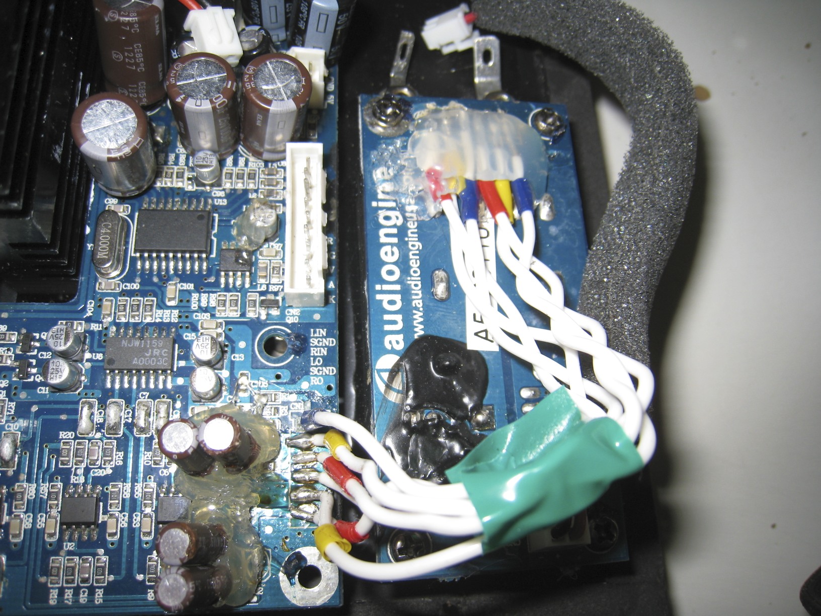
Basis:
(Input/output capacitor & resistors)
 (Brief Layout)

CAPACITOR RATING
Both Stock Ceramic and Polymer Capacitors are 10uF 25V.
Bypass: (Doing it)
4 Ceramic Capacitors & 2 Ceramic Capacitors are bypassed with a wire. (C9/C10/C7/C8/C18/C17)
2 Polymer Capacitors are bypassed with a wire. (C39/C40)
NOTE: You do NOT need to remove the capacitors that you are bypassing. Just simply use a wire from point A to point B.
I chose to remove mine. This may or may not apply to you.
Setup:
 Before Removal: How to remove polymer capacitors
:
http://pink.myshoesaretootight.com/mirrors/amiga.serveftp.net/Replace_capacitor.html
 Removal Begins: (wet soldering iron tip, touch tip to joint, with finger or clamp, pull slightly to opposite side)
 Removal Finished: (Be careful, don't force it too hard, the pcb leads will rip off)
 Capacitors Removed:
 Bypass wire: (Leftover 16AWG SPOFC)
 Cut Wire: (strip wire, tin wire with solder, and cut into 4mm bits)
 Bypass Finished:
Top View:
Bypass Finished:
Top View:
 Front View:
 Left Side View:
 Upgrade: (Improving signal coupling capacitors)
2 Polymer Capacitors are replaced with 4 Elna Silmic II 22uF 25VDC Electrolytic Capacitors (C4/C21)
2 Polymer Capacitors are replaced with 2 Elna Silmic II 22uF 25VDC Electrolytic Capacitors (C3/C22)
Making two Polar Capacitors, Bi-Polar:

 Keeping Leads/Legs Shot Before Soldering: (Pre-Out)
Don't make it overly short
Keeping Leads/Legs Shot Before Soldering: (Pre-Out)
Don't make it overly short
 Adding Elna Silmic II Polar Capacitors: (Pre-Output)
Place polar capacitors to slot C21 and C22 on the pcb, and solder with the correct polarity.
These spots are located at the bottom right of the board vertically to one another.
I decided to bypass mine with a wire instead as there is no DC current measured (in the millivolts) which would be beneficiary in providing better sonics.
Note: C3 & C4 requires bipolar capacitors for future protection against DC voltages so it's best to have capacitors there.
Adding Elna Silmic II Bi-Polar Capacitors: (Amplifier Coupling/Input)
 Test First before using Hot Glue.
Use generous amount until they no longer wobble.
Test First before using Hot Glue.
Use generous amount until they no longer wobble.
A5+ Dampening Material Upgrade:
SECTION 4:
(Improving Bass with Dampening Material [Housing & Foam for wires])
Products Chosen:
Open Cell Foam For Housing: http://www.madisoundspeakerstore.com/acoustic-damping/dampers-foam-sheet-27-x-42-x-5/8/ (Dampening Material)
Defraction Ring For Tweeter: http://www.madisoundspeakerstore.com/acoustic-damping/dampers-felt-defraction-ring-for-tweeters/ (Dampening Material)
Adhesive: http://www.homedepot.com/buy/paint/caulking-sealants/dap-alex-plus-101-oz-all-purpose-caulk-clear-18072.html#.UQwQv6VZVyI (DAP Alex Plus Acrylic Latex Caulk Plus Silicone)
Supplies: (acoustic foam not shown)
 Filling The Gaps:


 Dampening Left Speaker:


Semi-Dampening Right Crossover
:


Dampening Right Speaker:


Completed
A5+ Finalization Stage:
SECTION 5:
(Finish Connecting Wires To All Input & Outputs)
LETS START WITH WHATS OPTIONAL.
(Improving wire quality from mini pcb to main pcb carrying input/out signal)


- crimp/dupont connectors are eliminated, straight solder (signal improvement)
- Improved wire quality (signal improvement)
- Amplifier IC's stock thermal paste changed to Prolimatech PK-3 (thermal improvement)
- Twisted wires lower electromagnetic interference (signal improvement)
TIME TO FINISH IT
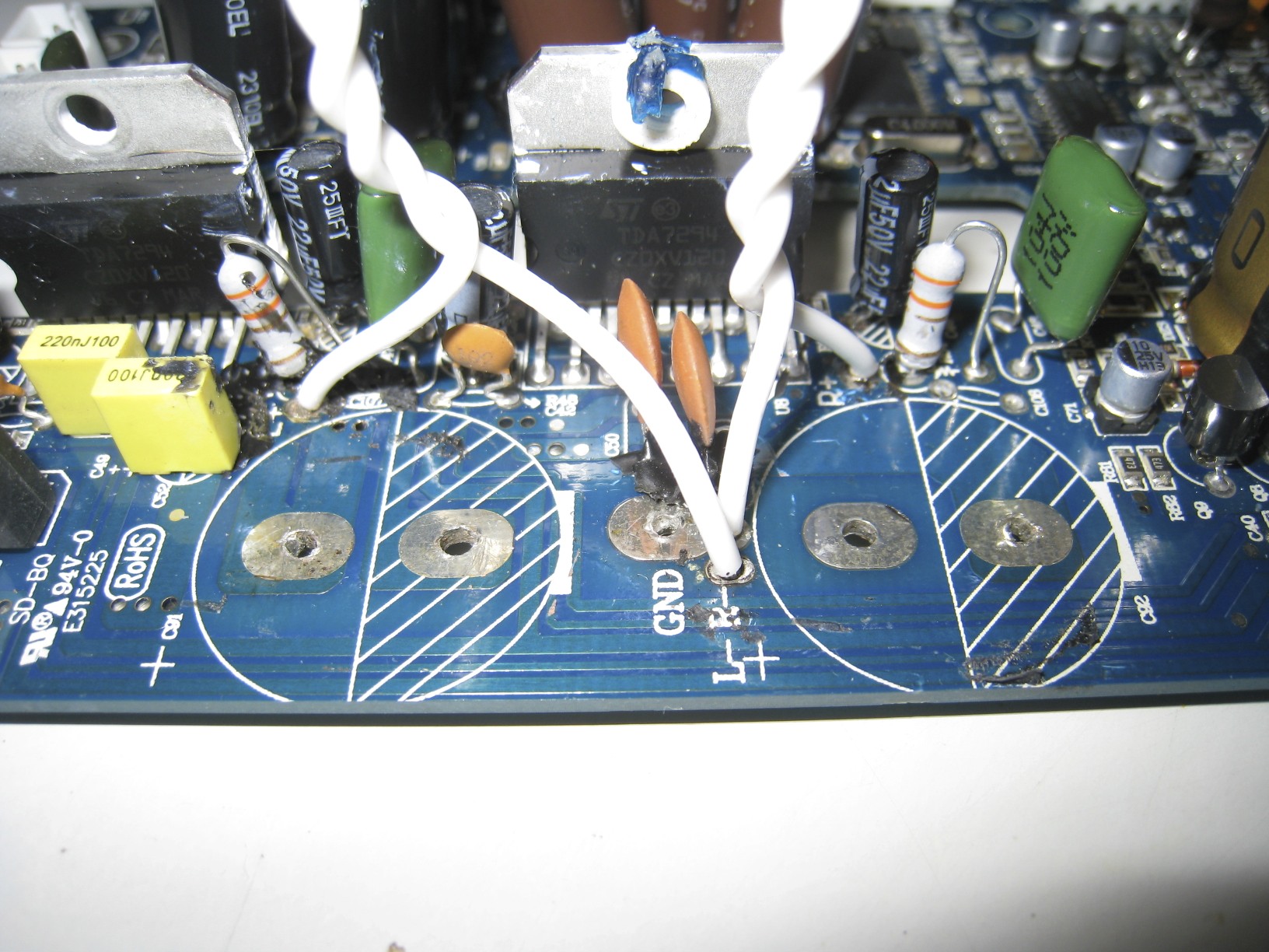
Assemble:


- Solder or use crimps to connect the wires to Woofer & Tweeter
- Add Hot Glue if using solder, to help hold the soldered areas in place (heat will loosen the joints).
- Put Woofer in, screw in the 4 screws.
- Fill Speaker Ring & Tweeter Cup with a generous amount of Silicone Caulk (or alternative adhesive), put on and push down, whip away excess.
Give it a day or two to dry.
- This will help dampen the cup/ring/woofer from vibrations, silicone is very flexible and will not crack, so continuous *loud* music playbacks will not hurt the adhesive nor distort your music.
FINAL RESULTS: (painted black gloss + extra ferro-fluid for tweeter magnets)

Completed
A5+ Sound Quality Review:
SECTION 6:
(Pros and Cons)
Let the testing begin!
May the odds be ever in your favor!
Before conducting this test, i would like to thank some people for making this mod possible.
- Transworld (XtremePlace) - for his electrolytic capacitor/wire/film capacitor/resistor/dampening upgrade IDEAS
- Handy Ray (Head-Fi) & Maxx_Power (diyAudio). - for his bypass/decoupling/coupling/dampening/adhesive upgrade IDEAS
Steve (Handy Ray/Maxx_Power) has been the biggest contributor to this mod, so if there's anyone to thank, it'd be him
TESTING EQUIPMENT
Speakers: Audioengine A5+ on DRUGS
DAC: NuForce DAC-100, ASUS Essence One "Muses" Edition (Modded), and Musical Fidelity M1
C7 Cable: Audioengine & Artemis Cables Power Cable
RCA Cable: Artemis Cables "Silver Bow" (Pure Silver) w/ Valab "Early Bird" Rhodium Plugs
Speaker Cable: Silver Plated OCC 24AWG Wires in Quad Litz soldered to CMC Silver Plated Pure Copper Spades.
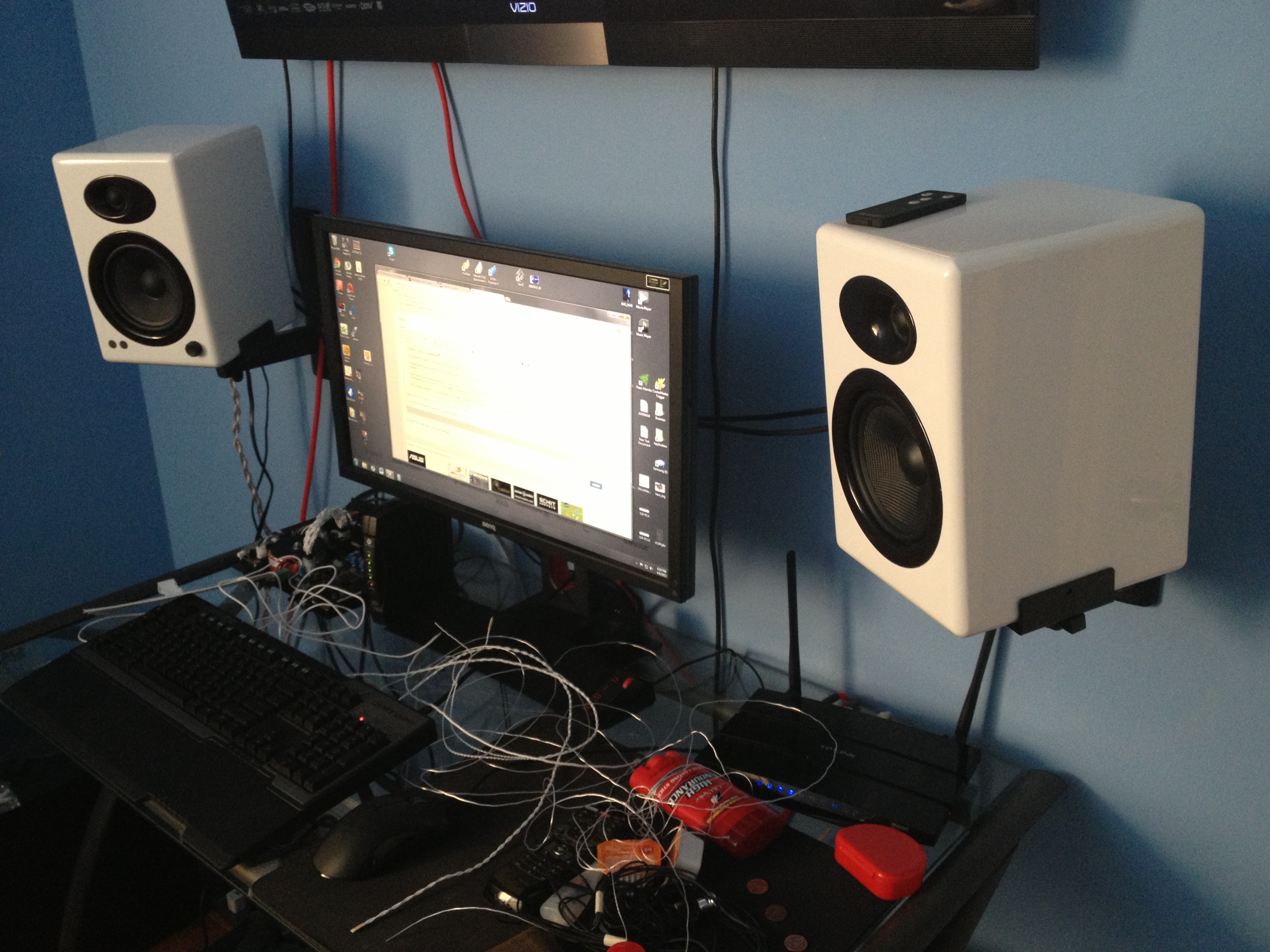
Speakers are wall mounted with Pinpoint AM-40B/B-Tech BT77 mounting sets.
They are 8 feet away from one another, horizontally, and 4FT from the ground.
[size=medium]
MUSIC FILES[/size]
Audio files are mainly 16bit/44.1khz with a few 24bit/96khz tossed into the mix.
Most of the tests are conducted with ZERO loss FLAC Files.
I will be using a iPhone 5 for pre-testing purposes (Burn in).
[size=medium]
BACKGROUND INFORMATION:[/size]
I've owned Audioengine speakers for nearly 3 years now,
Primarily started with the A5 until experiencing driver & tweeter noise, along with more pesky ones such as the "autosleep function" kicking in when music is being streamed.
From those various issues, i was able to RMA the speakers and receive a free upgrade to A5+ thanks to Marshall from Audioengine.
The original A5 had a good overall sound for the price.
Good punchy bass, sound separation, fast transient response from the kevlar woofers, treble that rolls off at the right moment, and that "Fun" sound.
When comparing the A5+ to the A5, since i've had it for years, i could tell the differences spot on.
First thing i noticed with the A5+ versus the A5 was the clarity and bass response.
The new horizontal intake from the back of the A5+ seems to have helped it improve on bass punch impact.
Now being rearranged differently, the A5+ also gained in clarity and micro-detail perhaps from the intake modifications or now that there is more room on the left side speaker due to the heat-sink being enlarged and outside of the enclosure.
Besides those two key improvements, i haven't really found any differences between the A5+ & A5, however just without the autosleep (now being manually controlled with remote) feature and tweeter noise now gone, i would have gladly paid $100 more for it.
[size=large]PROS:[/size]
After the mod/upgrade, there is no longer just a few key improvements like with the A5 > A5+.
There were a series of improvements that i've noticed with the A5+ after the mod was conducted.
They were:
- Bass/Treble/Transient Response
- Clarity
- Detail/Micro-detail
- Vocals
- Midrange
- Transparency/Neutrality
- Sound Stage
- Instrument/Vocal Separation (Imaging)
Yes, i noticed this within the first 5 minutes of playing a 16bit/44.1Khz FLAC file (Pop Music).
There were so many improvements that actually hit my sweet spot, i was flabbergasted.
Let's start from the top.
BASS was probably the largest improvement that i've had the joy of hearing.
Being a fan of mostly hiphop/pop and all music upbeat, it nailed my sweet spot hard with a 50-caliber round.
Before the A5+, the A5 was punchy, but not enough.
With the A5+, the punch was there, but there was no impact that my 6th sense could pick up.
Now with the upgrades, let me just say, my lungs tremble when i hear the bass response.
The transient response from the driver sure did a large ordeal for the bass after the upgrades had been done.
I cannot stretch this matter far enough, as i've never truly understood "impact", especially in headphones until i had auditioned the Audeze LCD-2 and LCD-3.
For speaker impact, i was sure, this was it.
The transitions of the treble were heightened and it's peaked took much longer before it smoothed out.
Perhaps because of this, did it play a roll into making the sound more neutral.
CLARITY/DETAIL improved significantly.
There were more micro-details when instruments were being played, end strokes vibration noises can now be somewhat heard, unique voices such as Amy Winehouse and other raspy artists now had more definition to their vocal character. The whole panoptic detail i felt was overall improved.
Definition for instruments, computer generated sounds, and vocals was like going from a 720P movie to a 1080P.
VOCAL/MID-RANGE/IMAGING/SOUND STAGE
I am addressing these four things at once, as i feel they belong/benefit with one another.
The speakers are put exactly to where they were before mods, the same place they were years ago, and yet, i feel as if the noise floor has lowered tremendously and that there was an expansion in the sound stage.
The sound stage widened and depth, blooming.
Imaging before the upgrades had been done made the vocals sound very narrow, as if there was a blank space somewhere in orbit between the vocal and background instruments/generated sounds.
Before i was able to sit between the speakers and hear vocal from the center, but a little far off between that point and coming to the speaker, there was no dynamic/expansive sound going towards that way that can be heard.
The upgrade expanded/stretched out the vocal, and with the help of clarity/detail, was i able to feel more of what the singer wanted me to hear, and because of that, the mid range was improved (being easily heard unlike before).
The best way to simplify this is that now there is a more full sound coming from the speakers.
You can say before was like 2D circle, and now it is a 3D sphere.
TRANSPARENCY/NEUTRALITY
All of the above may have contributed to making these speakers sound like neutral studio monitors.
I don't feel as though the bass response has helped in this matter for neutrality, but does so for keeping these speakers "Fun".
The sound now is less electronic and more analog.
Everything hits, and when it does, it feels genuine.
Now i could see why people eventually move on to more neutral sounding speakers (monitors).
[size=large]CONS:[/size]
- Time
- Money
- Health (smoke from soldering will affect your health)
- Breakage (possibility of breaking your speakers if not done correctly)
[size=large]CONCLUSION:[/size]
In the end, every upgrade that was made, had the attribute in which provided for me, an improved sound signature.
Everything new was more pleasant sounding than the old.
It was like transitioning from Fun Speakers to Neutral Monitors while still keeping most of the Fun.
Even with the new impactful punchy bass response that is now available, to me, it still sounds better when paired with a sub-woofer that is capable of hitting the 30-80hz region.
Just a little more sub-bass would be perfect.