Quote:
Great! Let me know when you have some results!
Well, I am not sure if you or anyone else will find the following graphs useful, but here is what I got using a pair of ~55.5 Ohm resistors as a test load on the headphone output (the 1/4" rear one, not the front panel which could be worse) of the Xonar STX, and with test methods discussed
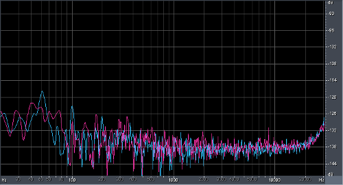
here. I did not use any $20000 gear, so take the results with a grain of salt (but they should not be very inaccurate if no mistake was made). All of these were created at a DAC sample rate of 48 kHz, as the DAC works worse at 44.1 kHz and its multiples, and the tests are focused on amplifier performance. The reference (0 dBFS) level is 2 Vrms, which allows for a fairly loud ~109 dB SPL with the LCD-2. At the highest gain and full volume, the card can output ~5.9 Vrms to the resistors; this agrees with what is expected from the ~7 Vrms unloaded maximum output and slightly more than 10 Ohms of output impedance, so there will probably be no issues with current limiting/lack of power, at least not with the version of the card I tested. The noise level (A-weighted) is -102.3 dB at 44100 Hz, and -109.5 dB at 48000 Hz; even the 44100 Hz value is low enough so that the actual noise SPL should be less than 10 dB and likely not audible in practice.
Edit: the headphone output has a DC offset of about 23 mV with this load; this is relatively high, but I do not think it is a problem for the LCD-2.
Frequency response (normalized), and noise floor (48 kHz, at 44.1 kHz, there would be additional noise from the DAC); ignore the slight bass roll-off, it comes from the ADC, not the output:


Harmonic distortion spectrum at 20 Hz, 1000 Hz, and 20000 Hz at 0 dBFS (2 Vrms). On the 20 kHz graph, the high noise floor is the result of noise shaping used in the ADC/DAC, you can ignore it. The TPA6120 distorts more at low frequencies, but fortunately low frequency distortion is also not very audible.
The bottom right graph shows the crosstalk vs. frequency (green: L->R, red: R->L); the main source of crosstalk is the ground impedance, therefore, it does not change much as a function of frequency. It is low enough not to be an issue.


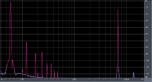
Intermodulation distortion, 19+20 kHz (1:1) and 60+7000 Hz (4:1). The latter is also shown with the distortion products around 7000 Hz zoomed in. These were also tested with full scale 5.6 Vpp signals.


THD up to 7th order with both channels driven vs. level (30 kHz bandwidth, red: 100 Hz, yellow: 1 kHz, green: 10 kHz), and frequency (red: 0 dBFS/60 kHz bandwidth, yellow: -10 dBFS/40 kHz bandwidth, green: -20 dBFS/20 kHz bandwidth). At low levels/high frequency, the result is mostly noise. However, the weird "bumps" on the 10 kHz THD vs. level traces are actual 3rd order distortion. Note that the X axis on the first graph is actually in mVrms units, ignore the "Hz":

 Edit: replaced the THD vs. level graph with a new one that is less noisy and extends to lower levels.
THD with only one channel driven at 0 dBFS, and 50 kHz bandwidth (green: left, red: right). The lower traces are cross-channel distortion, i.e. THD products leaking into the other channel. These are dominated by noise at high frequencies.


