Hi Alex! This is good news, since you know what they say about medical doctors - "first do no harm".
Alex and the other builders know I've stayed away from making any comments on how I think the booster board sounds or making any sound claims. That is all your guy's jobs!

There are a lot of folks here on the foum with critical listening ears much better than mine. I'm just the engineer.
If the booster does make any headphones or IEMs sound better it is probably due to some combination of the stuff that is objective (measureable) with the booster board:
* Like Alex says that 93% or so reduction in output DC offset from 3mV for the standard O2 to 30uV or so with the booster means that the transducers in headphones or IEMs stay much closer to their natural mechanical "zero" resting point. If this makes a difference at all in the sound it is more likely to be with sensitive IEMs than headphone. In fact, for my fairly sensitive AKG-K550s, I wrote their tech support once about the issue. The answer that came back was 3mV being no problem at all since the standard volume level is around 40mV and maximum around 130mV. 3mV just put the transducer diaphram slightly to one side. But I've read posts where people with some IEMs swear it makes a huge difference to have the transducer resting in the middle. So... you tell me from the listening!

* The latest version 3.0 with the relay completely eliminates all O2 turn-on and turn-off thumps with the one wire addition going from the booster to the O2 board. This won't change listening sound any, but at least the thumps are gone. One anoyance nailed.
* Double the slew rate as mentioned in posts above from the O2 amp's 3V/uS to the 6V/uS limit of the O2's input NJM2068 gain chip. As per the discussions above the digital 16/44 signal processing chain limits slew such that the O2's 3V/uS *should* be adequate, but there are certainly many other opinions here. Again, you guys tell me from the listening if there is a difference.
* +/-15Vdc upgrade capability for folks with high impedance and low sensitivity phones that can't get enough volume from the O2. This would be a fairly small subset of users.
* Those mezmerizing green LEDs!
They perform a couple of useful diagnositic functions. The LEDs are hooked in after the O2's power management mosfets vs. the O2's red which is before the mosfets. So when the green LEDs come on you know your mosfets have turned on and the O2 amp circutis are getting juice. And since one LED is on each power rail, if only one LED ever comes on you know you have lost on power rail, and even know which one based on which LED went dark. When the O2's batteries run down and the O2's power management circuit shuts it down, you finally have a way to know what has happened. The O2 red LED will still be on but both green LEDs will go off.
* Should be slightly lower noise and distortion from the datasheet numbers, but this is yet to be fully measured. I've recently bought one of the QA400 analyzers (essentially a USB soundcard in a box set up for distortion measurements) and ran some initial tests on both the standard O2 and one with the booster. To the limit of the QA400, which is 10 or 20dB noiser than a dScope or AP analyzer, the two looked essentially identical within the margin of error. The booster was just a tad better in THD+N, but again figuring in the margin of error it is a wash. But most likely both units are bumping up again that higher noise floor in the QA400. I'm in the process right now of stuffing a notch filter PCB I built to try to take those noise THD+N numbers down further. But again, the good news here is that the booster board did not appear to make the O2's THD+N any worse. Even if the THD+N numbers eventually do measure better than the stock O2 there is a good argument to be made as to whether that would even be audible or not. You tell me with the listening!
* Higher current drive capability for folks with low impedance low sensitivity headphones. Again this is likely to be a small subset of headphones or IEMS out there.
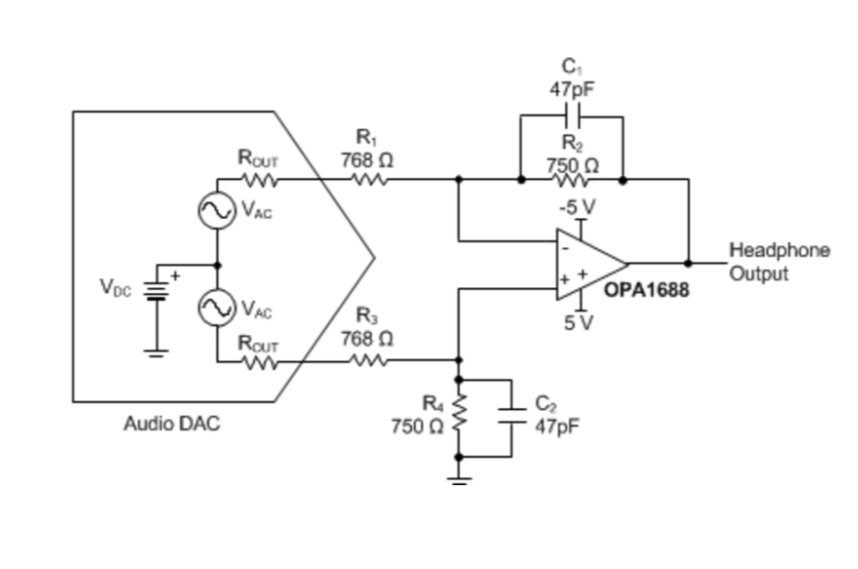
* Zero output impedance capability. The folks who have built booster boards should keep in mind they can short the four O2 1-ohm resistors straight across, as shown in the diagrams here, to get true zero ohms out. The stock O2 needs those resistors to balance up the two paralleled sections of the NJM4556A output chips. To make the booster board plug and play I designed it to use those 4 resistors as they sit when you plug in the board, so you still wind up with the O2's 0.5 ohm output resistance. But the booster chips don't need any resistor. You can just short those right across underneath the O2. Whether having zero ohms out vs. 0.5 ohms makes any difference in the sound, well... you tell me with your listening!