Brief Odac impressions
May 26, 2012 at 5:35 PM Thread Starter Post #1 of 2,018

MikeW

Headphoneus Supremus
Joined
Nov 4, 2005
Posts
1,789
Likes
243
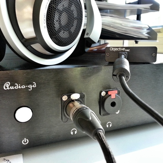
Got my Odac module in from JDS Labs, installed into my O2. Some brief thoughts :
 
Clean clean clean
non-offensive treble, but great resolution
tight, controlled, impactful bass.
resolution
dead quiet, silent
unforgiving
warm
detailed
easy listening
plug n play, no skipping, no hiccups, windows recognized instantly, and was good to go in ~5 seconds.
24 bit, with close to 20 bit resolution ~ software volume control becomes viable without loss of detail.
 
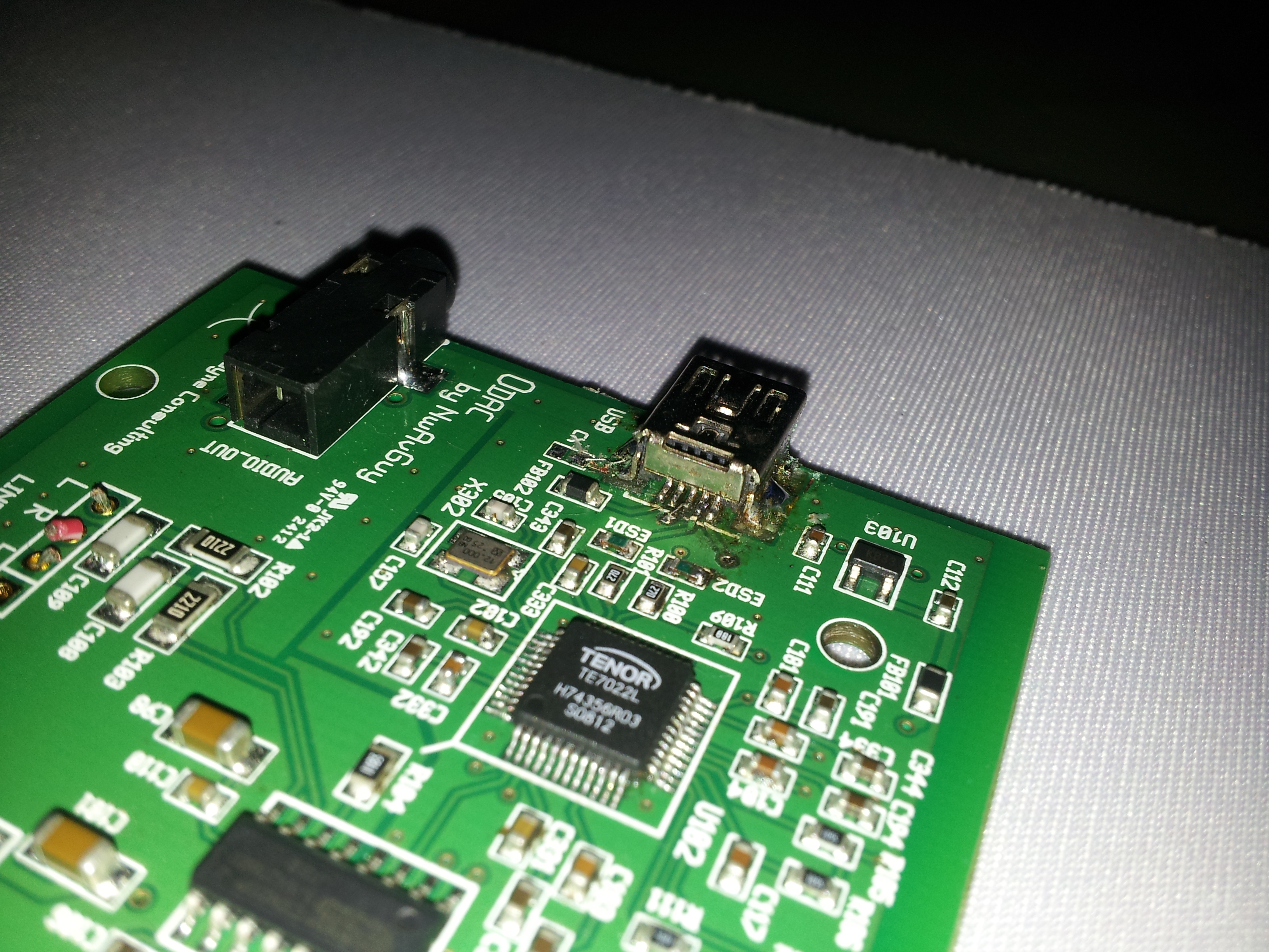
It's tiny! All SMD! can be used with any amp, would be a great module to include in your favorite DIY AMP to make it into an all in one.
I've only got a few hours listening, but these are some of the things that jumped out at me. More serious listening is needed.
 
May 28, 2012 at 2:38 PM Post #3 of 2,018
Got my JDS Labs Odac board a few days ago.
It IS tiny, albeit very nice construction.
What chaffs my hide is the lack of instructions to install an output jack.
 
Jack part number and supplier would be nice, and there is the doubt about
the solder pad bridges underneath that lead from the line-out traces/pads.
Does one solder in resistors, if so what value? Or does one bridge them with a blob of solder?
Or maybe forget about them, and leave them alone?
Also the negative pads for the line out are not clearly marked.
If one is handy with a DMM, you could check for ground-plane & trace continuity I guess.
 
Still I think that a simple instruction page should be included for the end user if the builder is going to leave components off.
Or maybe I am missing something here? Could this info already be posted somewhere?
 
Anywho, Ima gonna solder it up and box it as I see fit, cant wait to hear the wunerful music! 
 
May 28, 2012 at 3:17 PM Post #4 of 2,018
Thought I'd add - on the plus side, the JDS Labs offering includes the oddball USB cable with the mini-B connector.
Just wish they would mention it in their product offering, I almost went out and bought one while anticipating delivery of my Odac.
 
The Canadian distributor offers the Odac with a USB cable AND the 1/8 inch mini jack (not soldered to the board).
 
Edit - added the following:
 
Just fired the Odac up. What the OP said. Well worth the price of admission.
Good sounding unit, gonna need more time with it to form impressions.
I am comparing it to the HRT MS2 and MS2+ DACs, running a STAX SRS-2050 system.
 
May 28, 2012 at 11:28 PM Post #5 of 2,018
I'm listening to my new ODAC that I installed this afternoon in one of my O2s.
 
The install is not plug and play.
The ODAC board fits in the place of the batteries as designed.
The wire routing between the ODAC and O2 board takes a bit of
head scratching. The O2 amp board wasn't designed for easy
plug and play connection with the new ODAC. You have to pick up 
Left-Right-Ground from underneath the O2 board under the input jack
and route the wires to the top side of the amp board. I ended up routing
3 runs of 24g navships wire squeezed through the pcb lead holes for P1.
I cut the input jack traces as described in Voldemort's blog and the
switching between input jack and onboard ODAC works as expected.
 
My WinXP desktop recognized the ODAC as "odac" and configuration
went quickly. Nice that the USB interface was programed to identify
itself to Windoze as "odac' rather than "USB audio device" like every other
DIY DAC project I've done. Downside is that ASIO4ALL won't play
through the ODAC. It may take some software fiddling to get it to work.
I have no problem with ASIO4ALL playing with a AMB y1, y2, grubDAC
or Alien DAC, so the ODAC is a bit different.
 
I've been listening to the ODAC for a couple hours now. So far I'm using
HD800's and playing mp3s CD rips, mostly 256kb and 320kb so no
higher sample rates or bitdepth. So far nothing jumps out audibly, either
pro or con with the sound. I'm looking forward to comparing it with my
other DIY dacs; I have a TP buffalo, buffalo II, amb Y1, Y2, and a GrubDac
to compare it to. Eventually I plan to install the ODAC line out jack and 
then will be able to run it through the paces using other "higher end" amps. 
 I'm not the most golden eared listener though and have
a difficult time telling any difference between the DAC's I have.
 
May 29, 2012 at 8:19 AM Post #6 of 2,018
Quote:
I'm listening to my new ODAC that I installed this afternoon in one of my O2s.
 
The install is not plug and play.
The ODAC board fits in the place of the batteries as designed.
The wire routing between the ODAC and O2 board takes a bit of
head scratching. The O2 amp board wasn't designed for easy
plug and play connection with the new ODAC. You have to get pick up 
Left-Right-Ground from underneath the O2 board under the input jack
and route the wires to the top side of the amp board. I ended up routing
3 runs of 24g navships wire squeezed through the pcb lead holes for P1.
I cut the input jack traces as described in Voldemort's blog and the
switching between input jack and onboard ODAC works as expected.
 
...snip

 
For the input, you can directly solder to the P1 pad through holes (Ground is the center).  There's no need to solder to the underside of the input jack on the O2.
 
May 29, 2012 at 9:40 AM Post #7 of 2,018
Here is the PN for the output jack...
 
3.5mm Digikey CP-3523SJCT-ND
 
its also being sold on the JDS Labs site...
 
Seems the offical site for the ODAC is at diyaudio.com   then search for ODAC...   the boards are just now shipping...  
 
JDS is also selling a housed version... so it works with any amp...  looks good... 
 
 
May 29, 2012 at 2:20 PM Post #8 of 2,018
Quote:
Here is the PN for the output jack...
 
3.5mm Digikey CP-3523SJCT-ND
 
its also being sold on the JDS Labs site...
 
<snip>
 
Thanks for the info!
I also noted that the install instructions for the jack is listed there on the JDS Labs DIY parts page.
(re: info on bridging the solder pads with jumpers etc...)

 
May 29, 2012 at 4:02 PM Post #9 of 2,018
Quote:
 
For the input, you can directly solder to the P1 pad through holes (Ground is the center).  There's no need to solder to the underside of the input jack on the O2.

If you wire directly to P1 pads, the ODAC is hard wired to the input of the amp all the time.
If you wish to have the input switch built into the input jack socket function, i.e jack in an
external source disconnects the ODAC, jack removed connects the internal mounted ODAC,
then you must cut the traces and wire to pins 3 & 4 on the underside of the O2 pcb
for L & R out of the ODAC.
 
If you wire the ODAC directly to P1, a potential problem is if you connect an external source
and forget  and also have the ODAC powered and playing as well. This wires the
outputs of the two sources directly together. The two sources
will "fight" and over draw current from one or the other with potential damage.
 
So yeah, you can wire to P1, but I wouldn't do it unless the O2 amp is wired as a
ODAC amp only. Murphy's law will eventually bite you otherwise.
 
May 29, 2012 at 9:13 PM Post #10 of 2,018
Possible problems that should be addressed asap ~
 
Foobar Defaults to 24 bit, 44.1 (WASAPI)
 
Windows Audio defaults to 16 bit, 44.1
 
Windows software volume control still works. Ergo  - windows resamples to 16/44.1 by default. This is baaad mojo, and plainly audible.
 
Solution: Change windows audio to 24 bit, 44.1, or otherwise Sync Foobar/Windows Audio. And/or find a way to bypass the windows stack completely. I have not yet tried Kernal Streaming, but can't accomplish this with WASAPI, which is a bit odd.
 
Windows7 64 bit.
 
i wired mine up directly to P1, but it sounds like Bada Bing's method is the correct one, i'll likely change mine, thanks for the heads up.
 
May 29, 2012 at 10:29 PM Post #11 of 2,018
It's set and forget unless you actually have stuff above 44.1 since it won't resample stuff at the SR you set the shared mode to.  If you have a mix of 44.1 and 96 (the USB chip won't do 88.2) then you can just let foobar/WASAPI take care of the SR.  If you've got stuff at 88.2 then you'll need a good resampler like SoX but something like 99.9% of digital music is in 16/44 so it shouldn't be that big of a deal to most people.
 
Also disabling the volume control would be a waste since the whole point of a 24 bit DAC chip was to allow headroom for digital volume control.  The Win7 SRC does still suck but the 32 bit FP volume doesn't hurt anything.
 
May 29, 2012 at 11:26 PM Post #12 of 2,018
Quote:
If you wire directly to P1 pads, the ODAC is hard wired to the input of the amp all the time.
If you wish to have the input switch built into the input jack socket function, i.e jack in an
external source disconnects the ODAC, jack removed connects the internal mounted ODAC,
then you must cut the traces and wire to pins 3 & 4 on the underside of the O2 pcb
for L & R out of the ODAC.
 
If you wire the ODAC directly to P1, a potential problem is if you connect an external source
and forget  and also have the ODAC powered and playing as well. This wires the
outputs of the two sources directly together. The two sources
will "fight" and over draw current from one or the other with potential damage.
 
So yeah, you can wire to P1, but I wouldn't do it unless the O2 amp is wired as a
ODAC amp only. Murphy's law will eventually bite you otherwise.

If you look at the schematic, you'll see that wiring to P1 is the same as wiring to the underside of J2.  You cut the traces if you have J2 installed in order to defeat the input mute when nothing is plugged into J2.
 
May 30, 2012 at 3:08 AM Post #13 of 2,018
No, wiring to P1 are the same connection as wiring to pins 2 & 5  of the switched
jack J2. Connecting this way hard wires the the ODAC connection to the same
traces as the external source input of J2. If you wire it that way and try to run the
ODAC simultaneously with an external source plugged in, it will do exactly as
I posted; the two sources outputs are hardwired together.
 
The J1 jack socket has a two pole switch function that "breaks" upon insertion of
a Jack and "makes" on withdrawal of a jack. Before the traces on the O2 pcb
are cut, when the J2 switch poles "make" on jack withdrawal, the switch shorts
the amp inputs to ground. If you wire the ODAC to P1, you must cut the traces
to keep the ODAC outputs from being shorted to ground when no jack is plugged
in, but P1 is wired directly to pins 2 & 5 of the jack - which are the external source
input leads.
 
The "correct" way to wire the ODAC is as I have post - connect to J2 pins 3 & 4
located on the underside of the O2 PCB under J2. And cut the traces, which is required
in any case. Wiring this way insures that there is no possibility of two sources outputs
wired together. This isn't something I've made up, it is mentioned on Voldemort's March
blog post about the ODAC (which is not allowed to link here). Perhaps Voldemort
will post detailed ODAC installation soon which will clarify the details better than I'm able. 
 
O2 INPUT SWITCHING: Those who only want a USB headphone DAC
(like the FiiO E10 or NuForce uDAC-2) can simply wire from the output
header of the ODAC to the P1 input header on the O2 board. But for
those who still want to use other sources (like an iPod, etc.) with their O2,
you can have your cake and eat it too. Once you cut the traces shown
to the right you can wire the ODAC to terminals 3 and 4 of the input jack.
These lead to internal switches in the jack and will connect the ODAC
only when nothing is plugged into the O2.
 

Users who are viewing this thread

Back
Top