


francisdemarte
500+ Head-Fier
- Joined
- Mar 19, 2009
- Posts
- 929
- Likes
- 23
Do you still have your old regulators? Can you swap them in place of the LM337 to test?
Hi Bla,
A. I checked the volatges on the regulators again and they are:
LM317 - Vadj is 2.4V, Vin is 23.7V, and Vout is 3.6V
LM337 - Vadj is 0.0V, Vin is -23.7V, and Vout is -1.27V
According to your measurements, it looks like they're blown?
B. At the 47ohm resistors before the opamp, I'm getting two different reading on both resistors. It's 3.6V on the Left and -1.2V on the Right.
C. R2's seem fine. Should I swap them out for the 13V zeners I ordered?
D. But the Tantalum that was connected to LM337 ADJ pin is ringing when I do a continuity test so thats blown, right?
E. DC offset on the headphone jack is 160mv.
Do not plug in your headphones. This offset is almost to big for speakers!
1. Pull out tantalum capacitors and measure Vout. Regulator can work without Cadj (tantalums) and LM will show good Vout voltage if tantalums were bad. If you have multimeter in the same time, you can measure capacitance on pulled out tantalums. But watch out for polarity. Tantalum capacitors will blow of if there is reverse polarity for more than 2% of nominal value.
Yes. It is strange if measure resistance over R2 and get ringing. Probably blown tantalum. If there were zener diode instead R2 resistor, it would protect tantalum because zener diode wouldn't allow voltage over its nominal value (12V, 13V or any voltage that your zener has). Also zener wouldn't allow reverse voltage that usually kills tantalum capacitors.
2. If Vout is still bad (without tantalum) then you can cut out old LMs and install a new one. Leave nodes (legs from old LM) in PCB. Measure Vout again.
3. If Vout is still bad then you try to see what is happening with capacitors after regulator (FC). Simple test is, after turning the amplifier on, to check voltage on capacitor cap (top position where cross is - where capacitor pops if it is under great overvoltage or stress). Two capacitors must have very very low voltage on their cap (two capacitors connected after positive LM317) and two must have negative voltage close to Vout (two connected after negative LM337).
Awesome news!
I hope Milky also sees this and gets his LC up and running too.
PS: One day I should consolidate all the BlaBlaBla mod's and put them on the first page.
I just noticed that this thread is almost 1000 posts!
Hi Bla and francis,
I never plugged anything into the amp after the accident happened.
I pulled the tantalums out. The LM337 tantalum is blown. The other one (LM317) is not blown. What is the orientation of the tantalum that should go into the amp? I thought they were non-polar.
Here are the voltages after I removed the tantalums and four zeners installed:
LM317 - Vadj is 13.2V, Vin is 21.7V, and Vout is 14.5V
LM337 - Vadj is -12.8V, Vin is -21.7V, and Vout is -14.1V
Another thing, ALL leds DO light up now.
Lastly, DC offset is about 14-16mV after I plugged in a new OPA2111KP.
HI francis,
I thought 15mV was safe enough for 600ohm headphones so I took a chance and plugged them in. SOUND! lol.
IT sounds good..going to wait on things burning in before I make a judgement on the overall sound.
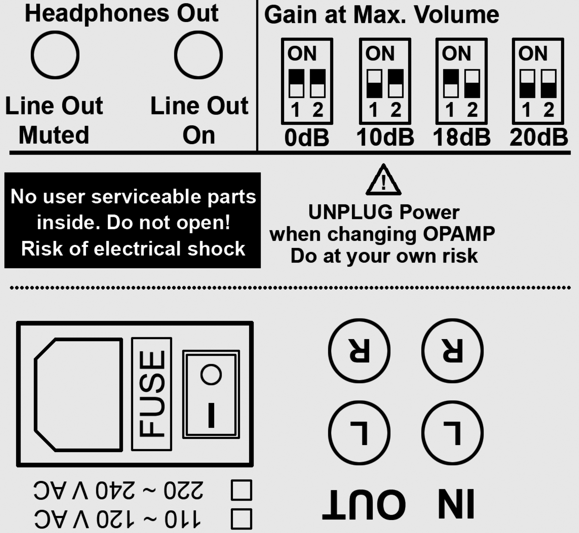
But, I see that the loudness level has gone down a little bit. I'm on 20db gain right now and I used to use 18db before to get the same level of output as right now. Any reason why this is happening?
15mV is safe for 600 Ohm headphones.
Loudness might be slightly lower because tantalum Adj capacitors give extra punch. It is interesting that tantalum capacitors give the most power to the sound (if we compare them to other capacitors). It seems that LM regulator is optimised to work with tantalum Adj cap. You should put in Adj tantalum (or something else) because without them your opamp supply suffers a bit. Transistors represent huge load compared to opamp. Big loads makes big voltage drops and that is represented as "noise" - to opamp that represents very small load. If that noise is in high frequency region big electrolytes can't smooth it because they are too slow (fast transistors will make more high freq noise and bigger peaks). So you need fast capacitors (Vout cap) Vout cap is 150nF. It smooths high frequency. Electrolytic cap (before transistors) are like energy tanks AFTER REGULATOR. They supply transistors with current when LM starts to sag because bigger demands.
Cadj has influence on entire picture because it doesn't smooth peaks and drops AFTER REGULATOR, it smooths bigger voltage drops that are made IN REGULATOR ITSELF because load after regulator. Here it is crucial that Cadj has leakage close to none, that has big current ripple, that has the same resistance over wide frequency range and that capacitance doesn't change too much with temperature. (Tantalum has all of this and it is very small. MKC/MKP is even better but 10x bigger and 20x more expensive. Electrolytic has big leakage, changes with temperature, variates with frequency and have bad ripple current ratio vs capacity )
Conclusion is that the bigger Cadj is, the less will output capacitors have to supply transistors and the less will small loads (opamp) suffer because big loads (transistors). But too big Cadj (over 20uF) is not good because it might damage LM regulator. Positive LM regulator will die if output voltage is bigger than input voltage - the case when current would flow in opposite direction (from out to in). Negative regulator is opposite than positive.
Sorry for bad english.
Very nice lesson! Thanks for the thorough info!
I put in new tantalum caps and it changed up the volts on the regulators. I'm getting ~42V on the input and output is still at 14.5 and 14.1 volts on both regulators. Is this normal?
ON the other hand, after all of these mods and improvements, I think the amp has come a long way of sound improvement. I actually heard the fibers of moving against the violin strings today. WOW!
...after all of these mods and improvements, I think the amp has come a long way of sound improvement. I actually heard the fibers of moving against the violin strings today. WOW!
I havn't kept up with this thread. Could you summerize what mods and improvements you performed?

")
I basically went through the entire thread about three times in order to condense all of the info. This is basically my first complete DIY modding project and mostly out of curiosity. It was painful but worth it IMO!
Below are the mods with Newark/Farnell part numbers (otherwise noted):
PSU:
Replaced the two 4700uf caps with United KMH caps (16M6799).
Replaced the ADJ caps with Sprague10uf tantalums (30C8841).
Replaced the R2 resistors with zener diodes as per BlaBla method (18C6023).
Replaced the regulators with Fairchild (58K8936/58K8937).
Replaced the four transistor 470uf caps with Panasonic FC (80K8337).
Signal Path:
Bypassed input caps with 6N copper wire.
Replaced the stock opamp with OPA2111KP.
Replaced the two opamp supply caps with Silmic II's.
Replaced the two small 0.022uf caps bypassing the Silmics with Philips (.027uf) Polystyrene caps. (Ebay)
Replaced the output 10 ohm resistors with Allen Bradley 1W carbon resistors (Ebay).
Replaced the 100pf caps with LCR Polystyrene caps (64K0006)
Let me know if I can be of any help if you plan to carry out any of the above!

