


castigar
Head-Fier
- Joined
- Oct 5, 2009
- Posts
- 68
- Likes
- 11
This is my first audio DIY, as well as my first guide here on Head-Fi.

I posted a while ago about how feasible this project would be, and since then, I've went out and bought all the stuff I needed to try this out. And the results: IT WORKS!

[size=small]Introduction and Idea[/size]
Balanced operation requires 4 channels going into your headphones (L+, L-, R+, R-). The stock AKG K702 has a 3-pin mini-XLR connector for detachable cables, and there exists many cables from people like ALO that replace the stock detachable cable that fit into this slot. However, the 3-pin forces only 3 wires (channels) going in to the headphones.
Thus, I got the idea to replace the stock 3-pin with a 4-pin connector. That way, I can actually get 4 channels into the headphones, and it keeps the detachable design that I like about the K702. I also built the cable from 4-pin mini-XLR to 4-pin XLR as well, which was relatively simple.
[size=small]Warnings and Notes[/size]
As a warning, this mod involves opening up the side of the headphones and pressing out the stock 3-pin mini-XLR jack, which is not a delicate matter. Specifically the part where you have to press out the stock jack. If you plan on doing this mod, you should be ready to order spare parts from AKG. I sure did.
Also, excuse me for not posting pics of the entire process, I got too excited when I got all the materials, and never stopped to take photos as I went along. I'll try to be comprehensive in my descriptions of what I did to make up for it.
[size=small]Materials and Tools[/size]
All materials used for this project was bought from Redco Audio, who offers some great prices for a lot of DIY projects.
Cable: 6ft of Mogami W2893 Miniature Quad Mic Cable
Heat Shrink: 6" of 1/4" Heat Shrink
Connectors:
Redco male 4-pin mini-XLR
Redco female 4-pin mini-XLR
Neutrik NC4MX-B (4-pin male XLR)
Neutrik NC4FX-B (4-pin female XLR)
Neutrik NP3C-B (1/4" TRS plug)
I had my own set of tools, but here's what you need for this mod:
soldering iron, solder, wire stripper and cutter (or a sharp knife!), multimeter (for continuity check), superglue, press (or is there some other way?)
[size=small]Part 1: Opening Up the Left Side[/size]
This is the first scary part. To get access to the wires, start by removing the left grille. Take a thumbtack, twist it counter-clockwise, and pull out. Be careful, you don't need to turn much for it to come out! And it also doesn't pull out very easily, so don't expect it to come falling off when you've turned it.
Once you open that, you should see something like this:

Next, remove the two screws on the ear cup. Now to remove the ear cup and get access to the wires, you must pinch the sides of the ear cup and pull outwards. This part is quite hard, and you must use quite some force to get it out! You also have to unsnap the headband guides from the ear cup. This is probably the first scary part. Once you get that you'll get to something like this:

(this image is actually after the mods, the wiring's already done in this one)
[size=small]Part 2: Desolder Internal Wires[/size]
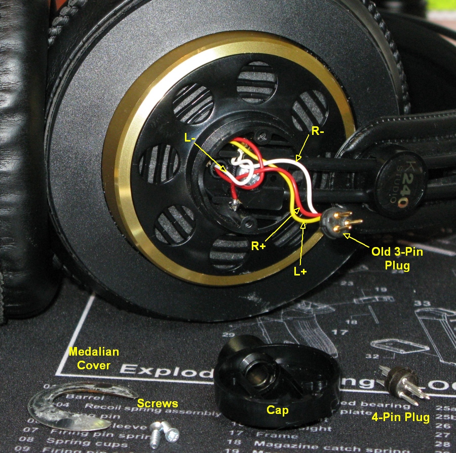
I don't have a proper picture for this, as the below picture was taken after I did the mod. But the stock AKG K702 has the common ground (L-, R-) soldered together. To get balanced configuration, we need to separate the two channels. If I remember correctly, the two ground wires are both white. The next picture shows which lead is which channel:

Also desolder the wires from the ear cup's stock 3-pin mini-XLR connector.
[size=small]Part 3: Press Out the Stock 3-pin Connector[/size]
Sorry I don't really have pictures for this. But the idea is to get the tiny little connector out (the small piece of plastic with the 3 pins through it). My roommate got the idea to use a press and a small metal rod to force it out of the ear cup. So we went to the machine shop and did so. We pressed the rod into the connector out through the cable slot in the ear cup. This was probably the scariest part of the entire project, but it worked out in the end. Though we got the ear cup a bit scratched up...
If there's any other way to remove it without brute force, please let me know!
[size=small]Part 4: Place in and Connect 4-pin Connector[/size]
First, take apart the male 4-pin mini-XLR connector, and there should be a small plastic piece with the 4 pins through it. This will replace the 3-pin one we removed.
First, solder the inner leads (the shorter ones) to the wires on the headphones. Refer to the above picture for which lead is which on the headphone. As for the pinouts for 4-pin XLR:
pin 1 - L+
pin 2 - L-
pin 3 - R+
pin 4 - R-
You should now have the 4-pin connector dangling from the side of the headphones. Now place the connector into the ear cup from the inside. This part is a bit delicate, so be careful. Once it's snugly in (for me, it didn't fully go in all the way like the previous 3-pin connector did), apply 2 or 3 drops of superglue to the sides of the connector on the inside of the ear cup.
The superglue makes sure that the connector doesn't wiggle when you connect a cable to it. I initially didn't apply the superglue, as I thought the connector was snug enough that it wouldn't wiggle, but when I tested it, it did. So do apply some superglue!


At this point, we're done with modifications to the actual phones. So, snap the earcup back into place (also kinda scary). Then replace the two screws, and replace the left grille we removed.
[size=small]Part 5: Build Cables[/size]
This part has probably been documented all over the place, so I won't go into excruciating detail. I took the 6ft of Mogami W2893 I got and cut it down to make an additional adapter to 1/4" TRS for single-ended operation.
For the main cable, we just want 4-pin female mini-XLR to 4-pin male XLR (the large one). Pretty simple to make, but there's a slight annoyance here. The mini-XLR connector doesn't fit the Mogami cable entirely (with all the insulation on). I could only fit the 4 internal wires through the hole, so I had to use some heat shrink to insulate this and provide a bit of strain relief. This is also why I stripped more from the mini-XLR side.
1. Slide on the strain reliefs and clamps from both connectors first! Don't be like me and forget to do so for one connection, and then have to desolder the plug to get them back on!
2. Slide on the 1/8" heat shrink onto the cable as well, we'll need this when we're done to insulate the 4 wires at the mini-XLR end.
3. Remove all the insulation from both ends. Get about 3/4" from the regular XLR side, and about 6/4" from the mini-XLR side. For the Mogami, this means the outer rubber, the thin shielding wires, the paper-like wrapping, and the cloth-like threads. We want just the 4 internal leads. Strip a tiny amount from these leads, maybe about 1/8" or so.
4. Assign a lead color to a pin number. I used Red - pin 1, Blue - pin 2, White - pin 3, Black - pin 4.
5. Solder leads from both ends to the connectors according to your color assignment from the previous step.
6. Use a multimeter to test for connectivity from one end to the other. Make sure no wires from different channels are touching internally.
7. Screw on the outer plug onto both ends.
8. Position the heat shrink over the bare 4 wires at the mini-XLR end. Use a heat gun (or in my case, a hairdryer) to heat it up, and it'll shrink and fit snugly around the wires to provide strain relief and insulation.
End Result:

I also made a balanced female 4-pin XLR to male 1/4" TRS adapter so I can still use my current SE amp. This one's more or less the same as the previous cable, just much shorter, and you must connect pin 2 and pin 4 (L- and R-) to the ground lead on the TRS connector. The TRS connector's leads are connected like this:
ground (L- and R-) goes to the shielding ring
L+ goes to the middle lead
R+ goes to the top lead
When connected to the other cable I made:

[size=small]Final Thoughts[/size]
In the end, the mod turned out pretty well, I think. I can't really comment on how the cable I built compares to the stock cable, as I can't really ABX it: the stock one doesn't fit onto the new 4-pin connector. I'm not really a cable believer (don't flame me, please <__<), but I am intrigued by balanced operation.
Now all that's left for me to do is save up money for a balanced amp like the LD MKVII+ and a balanced DAC too... sorry, wallet.
I hope this helps for anything thinking about balancing their pair of these wonderful headphones! Please offer some critique and/or comments! Wondering how I did for my first DIY mod...
I posted a while ago about how feasible this project would be, and since then, I've went out and bought all the stuff I needed to try this out. And the results: IT WORKS!

[size=small]Introduction and Idea[/size]
Balanced operation requires 4 channels going into your headphones (L+, L-, R+, R-). The stock AKG K702 has a 3-pin mini-XLR connector for detachable cables, and there exists many cables from people like ALO that replace the stock detachable cable that fit into this slot. However, the 3-pin forces only 3 wires (channels) going in to the headphones.
Thus, I got the idea to replace the stock 3-pin with a 4-pin connector. That way, I can actually get 4 channels into the headphones, and it keeps the detachable design that I like about the K702. I also built the cable from 4-pin mini-XLR to 4-pin XLR as well, which was relatively simple.
[size=small]Warnings and Notes[/size]
As a warning, this mod involves opening up the side of the headphones and pressing out the stock 3-pin mini-XLR jack, which is not a delicate matter. Specifically the part where you have to press out the stock jack. If you plan on doing this mod, you should be ready to order spare parts from AKG. I sure did.
Also, excuse me for not posting pics of the entire process, I got too excited when I got all the materials, and never stopped to take photos as I went along. I'll try to be comprehensive in my descriptions of what I did to make up for it.
[size=small]Materials and Tools[/size]
All materials used for this project was bought from Redco Audio, who offers some great prices for a lot of DIY projects.
Cable: 6ft of Mogami W2893 Miniature Quad Mic Cable
Heat Shrink: 6" of 1/4" Heat Shrink
Connectors:
Redco male 4-pin mini-XLR
Redco female 4-pin mini-XLR
Neutrik NC4MX-B (4-pin male XLR)
Neutrik NC4FX-B (4-pin female XLR)
Neutrik NP3C-B (1/4" TRS plug)
I had my own set of tools, but here's what you need for this mod:
soldering iron, solder, wire stripper and cutter (or a sharp knife!), multimeter (for continuity check), superglue, press (or is there some other way?)
[size=small]Part 1: Opening Up the Left Side[/size]
This is the first scary part. To get access to the wires, start by removing the left grille. Take a thumbtack, twist it counter-clockwise, and pull out. Be careful, you don't need to turn much for it to come out! And it also doesn't pull out very easily, so don't expect it to come falling off when you've turned it.
Once you open that, you should see something like this:

Next, remove the two screws on the ear cup. Now to remove the ear cup and get access to the wires, you must pinch the sides of the ear cup and pull outwards. This part is quite hard, and you must use quite some force to get it out! You also have to unsnap the headband guides from the ear cup. This is probably the first scary part. Once you get that you'll get to something like this:

(this image is actually after the mods, the wiring's already done in this one)
[size=small]Part 2: Desolder Internal Wires[/size]
I don't have a proper picture for this, as the below picture was taken after I did the mod. But the stock AKG K702 has the common ground (L-, R-) soldered together. To get balanced configuration, we need to separate the two channels. If I remember correctly, the two ground wires are both white. The next picture shows which lead is which channel:

Also desolder the wires from the ear cup's stock 3-pin mini-XLR connector.
[size=small]Part 3: Press Out the Stock 3-pin Connector[/size]
Sorry I don't really have pictures for this. But the idea is to get the tiny little connector out (the small piece of plastic with the 3 pins through it). My roommate got the idea to use a press and a small metal rod to force it out of the ear cup. So we went to the machine shop and did so. We pressed the rod into the connector out through the cable slot in the ear cup. This was probably the scariest part of the entire project, but it worked out in the end. Though we got the ear cup a bit scratched up...
If there's any other way to remove it without brute force, please let me know!
[size=small]Part 4: Place in and Connect 4-pin Connector[/size]
First, take apart the male 4-pin mini-XLR connector, and there should be a small plastic piece with the 4 pins through it. This will replace the 3-pin one we removed.
First, solder the inner leads (the shorter ones) to the wires on the headphones. Refer to the above picture for which lead is which on the headphone. As for the pinouts for 4-pin XLR:
pin 1 - L+
pin 2 - L-
pin 3 - R+
pin 4 - R-
You should now have the 4-pin connector dangling from the side of the headphones. Now place the connector into the ear cup from the inside. This part is a bit delicate, so be careful. Once it's snugly in (for me, it didn't fully go in all the way like the previous 3-pin connector did), apply 2 or 3 drops of superglue to the sides of the connector on the inside of the ear cup.
The superglue makes sure that the connector doesn't wiggle when you connect a cable to it. I initially didn't apply the superglue, as I thought the connector was snug enough that it wouldn't wiggle, but when I tested it, it did. So do apply some superglue!
At this point, we're done with modifications to the actual phones. So, snap the earcup back into place (also kinda scary). Then replace the two screws, and replace the left grille we removed.
[size=small]Part 5: Build Cables[/size]
This part has probably been documented all over the place, so I won't go into excruciating detail. I took the 6ft of Mogami W2893 I got and cut it down to make an additional adapter to 1/4" TRS for single-ended operation.
For the main cable, we just want 4-pin female mini-XLR to 4-pin male XLR (the large one). Pretty simple to make, but there's a slight annoyance here. The mini-XLR connector doesn't fit the Mogami cable entirely (with all the insulation on). I could only fit the 4 internal wires through the hole, so I had to use some heat shrink to insulate this and provide a bit of strain relief. This is also why I stripped more from the mini-XLR side.
1. Slide on the strain reliefs and clamps from both connectors first! Don't be like me and forget to do so for one connection, and then have to desolder the plug to get them back on!
2. Slide on the 1/8" heat shrink onto the cable as well, we'll need this when we're done to insulate the 4 wires at the mini-XLR end.
3. Remove all the insulation from both ends. Get about 3/4" from the regular XLR side, and about 6/4" from the mini-XLR side. For the Mogami, this means the outer rubber, the thin shielding wires, the paper-like wrapping, and the cloth-like threads. We want just the 4 internal leads. Strip a tiny amount from these leads, maybe about 1/8" or so.
4. Assign a lead color to a pin number. I used Red - pin 1, Blue - pin 2, White - pin 3, Black - pin 4.
5. Solder leads from both ends to the connectors according to your color assignment from the previous step.
6. Use a multimeter to test for connectivity from one end to the other. Make sure no wires from different channels are touching internally.
7. Screw on the outer plug onto both ends.
8. Position the heat shrink over the bare 4 wires at the mini-XLR end. Use a heat gun (or in my case, a hairdryer) to heat it up, and it'll shrink and fit snugly around the wires to provide strain relief and insulation.
End Result:
I also made a balanced female 4-pin XLR to male 1/4" TRS adapter so I can still use my current SE amp. This one's more or less the same as the previous cable, just much shorter, and you must connect pin 2 and pin 4 (L- and R-) to the ground lead on the TRS connector. The TRS connector's leads are connected like this:
ground (L- and R-) goes to the shielding ring
L+ goes to the middle lead
R+ goes to the top lead
When connected to the other cable I made:
[size=small]Final Thoughts[/size]
In the end, the mod turned out pretty well, I think. I can't really comment on how the cable I built compares to the stock cable, as I can't really ABX it: the stock one doesn't fit onto the new 4-pin connector. I'm not really a cable believer (don't flame me, please <__<), but I am intrigued by balanced operation.
Now all that's left for me to do is save up money for a balanced amp like the LD MKVII+ and a balanced DAC too... sorry, wallet.
I hope this helps for anything thinking about balancing their pair of these wonderful headphones! Please offer some critique and/or comments! Wondering how I did for my first DIY mod...

")
