Latest Thread Images


Featured Sponsor Listings

You are using an out of date browser. It may not display this or other websites correctly.
You should upgrade or use an alternative browser.
You should upgrade or use an alternative browser.
Bravo Audio - funny looking little tube amps
- Thread starter ear8dmg
- Start date

- Joined
- May 29, 2006
- Posts
- 425
- Likes
- 36
I've ordered a G2 Indeed, should be fun to play with.
KeeChoon
New Head-Fier
- Joined
- Jul 13, 2009
- Posts
- 36
- Likes
- 0
Need some help here. Had replacing the output caps of my Bravo V2 with 1000uf Muse and removed the pot, wiring it to a Alps Blue Velvet. After these mods, there is nothing from the right channel at all. The pads of the cap next to the 3.5mm input did lift but the connection seemed fine still. Have check the wiring for the pot and its correct. Any ideas anyone?
Avro_Arrow
MOT: Soundwerx Designs
- Joined
- Apr 8, 2010
- Posts
- 2,211
- Likes
- 56
Quote:
Check the continuity for the lifted pad with an ohm meter.
Did you observe the polarity of the output capacitors when you replaced them?
Lastly, remove and replace the tube...the socket seems to be a bit touchy sometimes. One last thing to check...do both heaters in the tube still glow?
Good Luck!
| Originally Posted by KeeChoon /img/forum/go_quote.gif Need some help here. Had replacing the output caps of my Bravo V2 with 1000uf Muse and removed the pot, wiring it to a Alps Blue Velvet. After these mods, there is nothing from the right channel at all. The pads of the cap next to the 3.5mm input did lift but the connection seemed fine still. Have check the wiring for the pot and its correct. Any ideas anyone? |
Check the continuity for the lifted pad with an ohm meter.
Did you observe the polarity of the output capacitors when you replaced them?
Lastly, remove and replace the tube...the socket seems to be a bit touchy sometimes. One last thing to check...do both heaters in the tube still glow?
Good Luck!
KeeChoon
New Head-Fier
- Joined
- Jul 13, 2009
- Posts
- 36
- Likes
- 0
Quote:
Polarity was correct, had tried 2 other tubes with the same result. Will look into the heater part later tonight. As for the lifted pad, I had tried wiring it to the next point it was connected to but no luck.
Anyway is the side with problem the exact right side for the output?
Thanks!
| Originally Posted by Avro_Arrow /img/forum/go_quote.gif Check the continuity for the lifted pad with an ohm meter. Did you observe the polarity of the output capacitors when you replaced them? Lastly, remove and replace the tube...the socket seems to be a bit touchy sometimes. One last thing to check...do both heaters in the tube still glow? Good Luck! |
Polarity was correct, had tried 2 other tubes with the same result. Will look into the heater part later tonight. As for the lifted pad, I had tried wiring it to the next point it was connected to but no luck.
Anyway is the side with problem the exact right side for the output?
Thanks!
Slowmoe
New Head-Fier
- Joined
- Apr 18, 2010
- Posts
- 2
- Likes
- 0
I've come along this list of tube equivalents and aside from the usual are other tubes that are listed. Now I've tried to keep up with this post, but somewhere around 28 I just fast forwarded and I may have missed this being already mentioned.
Anyways attached is the list, which may not be new to people here (it may even be done from here?).
If you look it shows the following as been equivalents:
6N11 --> (was the stock China one it came with originally)
6922 --> (I ironically swapped for an electro-harmonix, only for it to become the default option, it sounds quite good for what I have at hand)
E88CC/ ECC88 --> (I also tried the JJ Gold Pins, even when trimmed and balanced, I didn't like its profile when compared to the Electro Harmonix)
6DJ8 --> (I haven't tried any tubes of this flavour)
6ES8 --> (I haven't tried any tubes of this flavour)
ECC189 --> (I haven't tried any tubes of this flavour)
Anyone tried any of those other variants? Also since I got someones attention, if I was to make an equalizer, would it be good to do this before the preamplifier or after? I think it would be easier and better to do what needs to be done to a signal closest to the point of the source ... anyone have insight as to which option is better?
Ohh and first post, go easy on me folks
 .
.
EDIT: Oish sorry uploaded the wrong file before, sorry if I confused anyone. The file is too big, but the excel spreadsheet can be had here:
http://www.tubebbs.com/tubedata/othe...valents_AS.xls
Anyways attached is the list, which may not be new to people here (it may even be done from here?).
If you look it shows the following as been equivalents:
6N11 --> (was the stock China one it came with originally)
6922 --> (I ironically swapped for an electro-harmonix, only for it to become the default option, it sounds quite good for what I have at hand)
E88CC/ ECC88 --> (I also tried the JJ Gold Pins, even when trimmed and balanced, I didn't like its profile when compared to the Electro Harmonix)
6DJ8 --> (I haven't tried any tubes of this flavour)
6ES8 --> (I haven't tried any tubes of this flavour)
ECC189 --> (I haven't tried any tubes of this flavour)
Anyone tried any of those other variants? Also since I got someones attention, if I was to make an equalizer, would it be good to do this before the preamplifier or after? I think it would be easier and better to do what needs to be done to a signal closest to the point of the source ... anyone have insight as to which option is better?
Ohh and first post, go easy on me folks
EDIT: Oish sorry uploaded the wrong file before, sorry if I confused anyone. The file is too big, but the excel spreadsheet can be had here:
http://www.tubebbs.com/tubedata/othe...valents_AS.xls
- Joined
- May 29, 2006
- Posts
- 425
- Likes
- 36
There are Russian 6H23P (Which I have, but not burned in enough to comment, other than to say it's not bad at least), and I believe there are some other similar Russian tubes that are reputedly good.
Avro_Arrow
MOT: Soundwerx Designs
- Joined
- Apr 8, 2010
- Posts
- 2,211
- Likes
- 56
Quote:
You forgot one of the most important modifications...Cathode bias bypass
capacitors. The value is not critical....something from 100uF up to 440uF @ 6.3 volts is enough. I stuck in a couple of 680uF @ 10 volt panasonics that I had
laying around. They go across the bias adjusting pots.
The self biasing for the tube does not work properly without them.
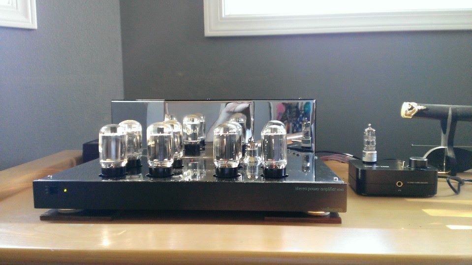
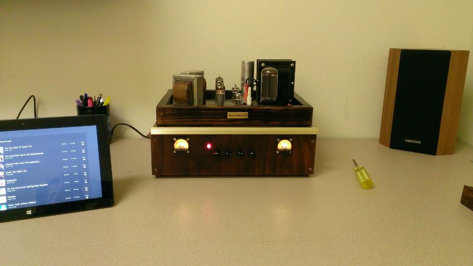
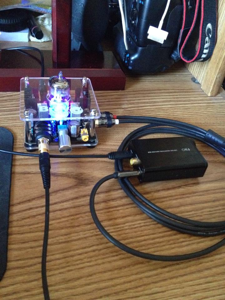
| Originally Posted by Judge Buff /img/forum/go_quote.gif I think you can tell my little mods from these three perspectives: |
You forgot one of the most important modifications...Cathode bias bypass
capacitors. The value is not critical....something from 100uF up to 440uF @ 6.3 volts is enough. I stuck in a couple of 680uF @ 10 volt panasonics that I had
laying around. They go across the bias adjusting pots.
The self biasing for the tube does not work properly without them.
Judge Buff
500+ Head-Fier
- Joined
- Dec 3, 2008
- Posts
- 913
- Likes
- 85
Quote:
I'm pretty sure that I forgot nothing...
I made every modification that I wanted to make. Self-biasing? If my Indeed V1 has self-biasing, I missed that when I read the product description last fall.
Post some pictures and let us SEE what you mean.
Those are pretty high values for bypass caps, aren't they? My output cap's only 470uF.
| Originally Posted by Avro_Arrow /img/forum/go_quote.gif You forgot one of the most important modifications...Cathode bias bypass capacitors. The value is not critical....something from 100uF up to 440uF @ 6.3 volts is enough. I stuck in a couple of 680uF @ 10 volt panasonics that I had laying around. They go across the bias adjusting pots. The self biasing for the tube does not work properly without them. |
I'm pretty sure that I forgot nothing...
I made every modification that I wanted to make. Self-biasing? If my Indeed V1 has self-biasing, I missed that when I read the product description last fall.
Post some pictures and let us SEE what you mean.
Those are pretty high values for bypass caps, aren't they? My output cap's only 470uF.
Judge Buff
500+ Head-Fier
- Joined
- Dec 3, 2008
- Posts
- 913
- Likes
- 85
Quote:
ECC88 is the European designation for the American 6dj8 and vice versa. E88CC is European for an American 6922 and vice versa. ECC189s are not drop-in compatible with 6dj8s. ECC188s are the same as 7308 Americans. I haven't tried any 6es8s, as I haven't seen any around. ECC88s/6dj8s rock in my Indeed! 6922s/E88CCs are generally smoother/softer sounding in my Indeed. PCC88s are 7V versions of ECC88s and work quite well in my Indeed @6.3V. Apparently a lot of folks like the EH 6922s, but JJ Teslas are apparently really POS.
| Originally Posted by Slowmoe /img/forum/go_quote.gif I've come along this list of tube equivalents and aside from the usual are other tubes that are listed. Now I've tried to keep up with this post, but somewhere around 28 I just fast forwarded and I may have missed this being already mentioned. Anyways attached is the list, which may not be new to people here (it may even be done from here?). If you look it shows the following as been equivalents: 6N11 --> (was the stock China one it came with originally) 6922 --> (I ironically swapped for an electro-harmonix, only for it to become the default option, it sounds quite good for what I have at hand) E88CC/ ECC88 --> (I also tried the JJ Gold Pins, even when trimmed and balanced, I didn't like its profile when compared to the Electro Harmonix) 6DJ8 --> (I haven't tried any tubes of this flavour) 6ES8 --> (I haven't tried any tubes of this flavour) ECC189 --> (I haven't tried any tubes of this flavour) Anyone tried any of those other variants? Also since I got someones attention, if I was to make an equalizer, would it be good to do this before the preamplifier or after? I think it would be easier and better to do what needs to be done to a signal closest to the point of the source ... anyone have insight as to which option is better? Ohh and first post, go easy on me folks
EDIT: Oish sorry uploaded the wrong file before, sorry if I confused anyone. The file is too big, but the excel spreadsheet can be had here: http://www.tubebbs.com/tubedata/othe...valents_AS.xls |
ECC88 is the European designation for the American 6dj8 and vice versa. E88CC is European for an American 6922 and vice versa. ECC189s are not drop-in compatible with 6dj8s. ECC188s are the same as 7308 Americans. I haven't tried any 6es8s, as I haven't seen any around. ECC88s/6dj8s rock in my Indeed! 6922s/E88CCs are generally smoother/softer sounding in my Indeed. PCC88s are 7V versions of ECC88s and work quite well in my Indeed @6.3V. Apparently a lot of folks like the EH 6922s, but JJ Teslas are apparently really POS.
Avro_Arrow
MOT: Soundwerx Designs
- Joined
- Apr 8, 2010
- Posts
- 2,211
- Likes
- 56
Quote:
Hi Judge Buff
The mods you have done so far are great!
This mod corrects a minor design flaw that the amps have. Here's the thing...
You know that electrons flow from the (negative) cathode to the (positive) anode.
This flow is controlled by the gate.
If the gate is positive compared to the cathode then electrons flow into the gate as well.
To prevent this, the gate is made negative compared to the cathode.
The method to do this in this case is to put a resistor between the cathode and ground. This is know as "self biasing". The problem is that as the current through the resistor changes in response to the input signal, so does the voltage at the cathode. The effect is to cause compression of the input signal. The bypass capacitor hold the voltage on the cathode steady and prevents this effect.
The result to your ears should be a more dynamic and punchier sound.
I attached the schematic of the amp with the new component drawn in in red.
I will have a picture for you later today if I can.
Happy listening!

| Originally Posted by Judge Buff /img/forum/go_quote.gif I'm pretty sure that I forgot nothing... I made every modification that I wanted to make. Self-biasing? If my Indeed V1 has self-biasing, I missed that when I read the product description last fall. Post some pictures and let us SEE what you mean. Those are pretty high values for bypass caps, aren't they? My output cap's only 470uF. |
Hi Judge Buff
The mods you have done so far are great!
This mod corrects a minor design flaw that the amps have. Here's the thing...
You know that electrons flow from the (negative) cathode to the (positive) anode.
This flow is controlled by the gate.
If the gate is positive compared to the cathode then electrons flow into the gate as well.
To prevent this, the gate is made negative compared to the cathode.
The method to do this in this case is to put a resistor between the cathode and ground. This is know as "self biasing". The problem is that as the current through the resistor changes in response to the input signal, so does the voltage at the cathode. The effect is to cause compression of the input signal. The bypass capacitor hold the voltage on the cathode steady and prevents this effect.
The result to your ears should be a more dynamic and punchier sound.
I attached the schematic of the amp with the new component drawn in in red.
I will have a picture for you later today if I can.
Happy listening!

Judge Buff
500+ Head-Fier
- Joined
- Dec 3, 2008
- Posts
- 913
- Likes
- 85
Quote:
Gotcha... a pic of the placement would be great. I'd probably need to put small film caps on the bottom of the PCB. I'm a true visual learner.
| Originally Posted by Avro_Arrow /img/forum/go_quote.gif Hi Judge Buff The mods you have done so far are great! This mod corrects a minor design flaw that the amps have. Here's the thing... You know that electrons flow from the (negative) cathode to the (positive) anode. This flow is controlled by the gate. If the gate is positive compared to the cathode then electrons flow into the gate as well. To prevent this, the gate is made negative compared to the cathode. The method to do this in this case is to put a resistor between the cathode and ground. This is know as "self biasing". The problem is that as the current through the resistor changes in response to the input signal, so does the voltage at the cathode. The effect is to cause compression of the input signal. The bypass capacitor hold the voltage on the cathode steady and prevents this effect. The result to your ears should be a more dynamic and punchier sound. I attached the schematic of the amp with the new component drawn in in red. I will have a picture for you later today if I can. Happy listening! |
Gotcha... a pic of the placement would be great. I'd probably need to put small film caps on the bottom of the PCB. I'm a true visual learner.
Avro_Arrow
MOT: Soundwerx Designs
- Joined
- Apr 8, 2010
- Posts
- 2,211
- Likes
- 56
Here is a picture of the Capacitor placement.
The positive side of the cap goes to the cathode and the negative side goes to ground. Mine are soldered to the bottom of the bias adjust pots.
The cathode sits about .5 volts above ground so a low voltage electrolytic, say 6.3 volts, is all you need. You are trying to achieve a corner frequency of 1 hz so the value is relatively large...100uF up to 440uF are common. Maybe calling it a "bypass" capacitor confuses people into thinking it is like a MKT you might use in the power supply, but it's job is more like the 10,000uF you have as you bulk supply capacitor.
This would be a good choice...it is an OS-Con with a very low ESR.
Digi-Key - 493-3066-ND (Manufacturer - PLE0J471MDO1)

Judge Buff
500+ Head-Fier
- Joined
- Dec 3, 2008
- Posts
- 913
- Likes
- 85
Quote:
Thanks! I have a ton of 16V 470s, 100s and 220s around here that are low ESR (though not as low as the one you linked). I'll try to rig something while I'm off from work this week. Once again, thanks for the info. I'll post results.
| Originally Posted by Avro_Arrow /img/forum/go_quote.gif Here is a picture of the Capacitor placement. The positive side of the cap goes to the cathode and the negative side goes to ground. Mine are soldered to the bottom of the bias adjust pots. The cathode sits about .5 volts above ground so a low voltage electrolytic, say 6.3 volts, is all you need. You are trying to achieve a corner frequency of 1 hz so the value is relatively large...100uF up to 440uF are common. Maybe calling it a "bypass" capacitor confuses people into thinking it is like a MKT you might use in the power supply, but it's job is more like the 10,000uF you have as you bulk supply capacitor. This would be a good choice...it is an OS-Con with a very low ESR. Digi-Key - 493-3066-ND (Manufacturer - PLE0J471MDO1) |
Thanks! I have a ton of 16V 470s, 100s and 220s around here that are low ESR (though not as low as the one you linked). I'll try to rig something while I'm off from work this week. Once again, thanks for the info. I'll post results.
Slowmoe
New Head-Fier
- Joined
- Apr 18, 2010
- Posts
- 2
- Likes
- 0
Hey how does this mod behave at full gain? I think the no-bypass reduced the gain ad this mod increases it. Might just place too much stress on the MOSFET at full amplification for too long. Also this might become more susceptible to loading effects, so it might have different gains with different loads, whereas now it is more stable.
Any one who modded care to try on full blast? Try with a load as well, not just an open-loop.
Any one who modded care to try on full blast? Try with a load as well, not just an open-loop.
Users who are viewing this thread
Total: 1 (members: 0, guests: 1)
