


lemonjelly
New Head-Fier
- Joined
- Feb 16, 2012
- Posts
- 28
- Likes
- 13
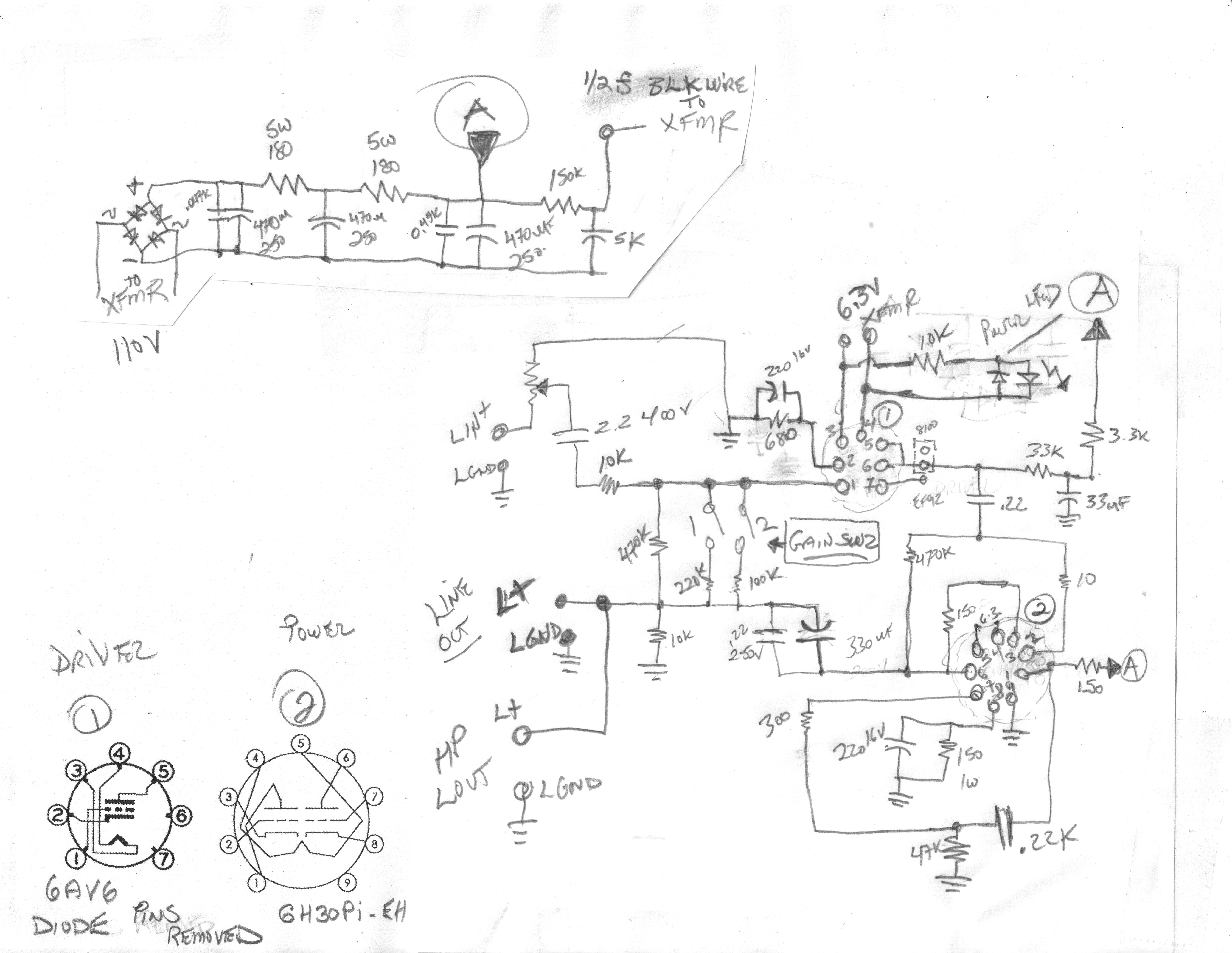
I've got the mk III version, which I use with a pair of HD650s, and have made quite a few changes since I first bought it (a couple of years ago). I started with trying to change the caps - basically following this thread - but found that the case really was pretty bad to work in. I ended up ditching the chassis for 1 that I built myself, that's about 3 times as big ! But for me it made sense as I wasn't really restricted by the cap size and it was much easier to do stuff and then change it again if it didn't work out. Cos it'll be easier I'll put in the schematic of the original mkIII amp, and it might be useful for anyone as reference when modding (I did this pretty quickly but it should be correct). I also about halfway along desoldered anything I needed from the PCB and went completely to point to point wiring (it meant I had more space and could position everything how I wanted).

Cos I switched out the caps so long ago I can't remember that well the differences that they made, they were definitely all positive, but the biggest differences from what I remember were with the change of the 0.22s and the inclusion of the 3.3uFs as bypass in the power section. Currently I have:
Russian K40-9s PIOs (I think) as replacement to the 0.22s, 3x K75-10s 3.3uF bypassing each PS cap, ampohm tinfoil 0.047uFs to replace the same in the PS section, panasonic 470uFs to replace the 3 x 330uF PS caps, Rubycon 330uF to replace the 220uF caps, 0.1uF teflon FT3s as bypass for the Rubycons and 0.68uF K75-10s to replace the same in each section.
I also had a 3.3uF Jantzen superior as input cap in each section (replacing the 2.2uFs), but ended up taking them out entirely as Sebastian had earlier in the thread. You have to be very careful of course if you're doing that cos from what I understand if your source has any DC offset, then this will get amplified and blow up your headphones basically... I also kinda messed up the wiring on the volume pot, and found that as I use it with a HTPC/DAC set up pretty much all of the time I was happy to just use the volume on the PC. So rather than buy a new pot, I soldered in resistors from the rca signal to ground and where the 2.2uF cap is. I think I've got a 2k to the 2.2uF, and a 330 to ground (I found I used about a range of 6->8:1 ratio on the original pot). The total value to use here from what I've read, seem to depend on the output impedance of your source (10 times that value seems to be the guidance). I'm using a DAC exclusively, which has about a 50 ohm value, and so I thought to play it safe I'd go to around 2k. I also just put in a single resistor of 80k instead of the gain resistors (the gains correspond to x3->69k, x4->83k, x5 ->150k, x10 ->470k).
Part of the reason I uprated the values of the caps above, was that those are the stock values for the mk IV (the 330uFs are 470 and 220uFs 330 in the IV). Other changes between the IV and III are the 120 resistors are all replaced by 150s on the IV, and the EF95 heaters are regulated.
Those changes were all good + I rolled tubes, settling on 6n6ps with the Mullard EF92 or the russian EF95s. But from the rolling thread (which is great) and what they've discovered I ended up switching the drivers to a Tung Sol 6SN7. The difference was immediately obvious, especially as far as bass and soundstage. Everything seemed a lot more real. The 6SN7 needs seperate power for the heaters so I just used a DC PSU I had (7.5V / 2A), which I found stayed stable at 6.35v when the tube was connected. After I made the switch I decided I wasn't really ever going to use the EF95/92s again, so I actually replaced the 2 sockets with the single octal (no more wires going everywhere).
After that I thought I'd have a play with some of the plate resistance/cathode bias settings for the 6SN7/6N6P. For the 6SN7 the plate bias is set by the 33k/1W resistors. I tried 40k, 16k and 10k. I didn't really notice much difference with the 40k, a big change with the 16k (I felt as big as the original change to the 6SN7 from the EF95/92s) and from the 16k the 10k was worse. With the 16k the sound stage seemed much better, and everything seemed more musical (toe tappability). I then changed the cathode bias resistors (the 680 for the 6SN7), going up and going down. I didn't really notice a huge difference sound wise. I then tried led bias instead, wiring in an led to drop voltage instead of using a resistor. This seemed to sound worse, but was probably because the led didn't have enough current to react linearly (the 6SN7 current was only about 3mA when the led really needs more than 5). Finally I tried using 2xAA rechargeable Nimh batteries (about 2.7v in series). This seemed to sound best to me (but the change wasn't as big as the change to 6SN7 or to plate resistor). With the led and battery it's as simple as replacing the 680 resistor and 220uF cap with whichever you're using, and wiring the +ve to pin2 of the EF95 socket, and -ve to gnd. With the 6N6P I didn't bother changing the plate resistor (which I think is probably the 120/1W R6 on schematic), but I tried different values for the cathode bias. I settled on 200 eventually, after trying battery/led/100/87/150/200, I didn't like the led or battery, and there didn't seem a huge difference between the other numbers.
Basically the above is changing the plate voltage, current and bias voltage of the tubes when you change the values. You can look at the curves for the tubes you're using and see what operating point you want to aim for. Generally increased cathode resistance means plate and cath v goes up, and current goes down, increased plate means plate/cath/current go down. For the plate resistance I'm not certain but from what I've read it seems like it affects the voltage swing (i.e. bigger the more dropped over the resistor) and gain. For the values I've got figures for, with plate resistance/cathode resistance:
6SN7 6N6P
33k/680 (2.4v) 3.5mA @ 85v 120/120 18mA @ 107v
33k/2.8v led 3.18mA @ 95 120/150 16.3mA @ 112v
39.8k/2.8v led 2.86mA @ 90v 120/87 20.3mA @ ~100v
39.8k/2k (4.45v) 2.225mA @ 118v
39.8k/2.7v battery 3.44mA @ 69v
16.5k/2.7v battery 5.4mA @ 115v
21.6k/2.7v battery 4.7mA @ 107v
As well for the 6N6P I went to an external PSU for the heaters, and changed the cathode resistor to 200. I found that sounded best and got figures for that of 16.5mA @ 128v, with the 16.5k/2.7v battery setting with the 6SN7. Mods that I've been looking at possibly doing are a CCS for the plate on the 6SN7 instead of the resistor (but I don't really know enough at this point), and cheap chokes in the PS section in place of the resistors (I've got space on top of the amp). I've also got a couple of 6AS7s on the way which will hopefully make a big difference. I keep meaning as well to replace the signal resistors with something other than the generic metal film I have currently.
Lonnnngggggg post, but I've had a lot of fun just trying different things with this amp - especially as a lot of these were pretty cheap to do - and of course I'm not suggesting that I understand everything that is going on. I've been learning as I've gone on so if there is anything I've done that's really stupid I'd appreciate people saying, but at this point the amp sounds great with headphones or as a pre amp.
Final edit: thought it would be useful to include the pin changes for 6SN7/6AS7 for the 7 or 9 pin sockets (all taken from the rolling thread, so thanks to those guys).
The 6n6p on the LD should be OK supplying up to about an amp, with the EF95s only able to put out 0.2-0.3A, so for the 6SN7s you can use the heater supply from the 6n6p socket, but otherwise for the 6SN7 in the EF95 socket, or the 6AS7s, you'll need an external power supply. The 6SN7 pulls 0.6A, and the 6AS7s pull 2.5A, both at 6.3v. You could potentially run 2 tubes from a 12v supply in series without a regulator (just make sure the current rating is high enough + check the voltage at the tube pins, 5.7-6.9v is OK). I also ran 2 6080s (6AS7 types) from a computer PSU 12v line in series, but it wasn't happy and started cutting out. But you're best buying a power regulator like this to make it all easier. Currently I've got a 19v/3.5A laptop PSU with a regulator, running the 2 6080s in parallel @ 6.3v each.
9 pin (6n6p) 6SN7/6AS7 6SN7/6AS7 7 pin (EF95)
1 (A1) 2 1 (G1) 1 (L)
2 (G1) 1 2 (P1) 5 (L)
3 (C1) 3 3 (C1) 2 (L)
4 (Heater) 7/8 4 (G2) 1 (R)
5 (Heater) 7/8 5 (P2) 5 (R)
6 (A2) 5 6 (C2) 2 (R)
7 (G2) 4 7 (Heater) Ext. heater
8 (C2) 6 8 (Heater) Ext. heater
9 (Screen - Gnd) -

")

