linuxworks
Member of the Trade: Sercona Audio
- Joined
- Oct 10, 2008
- Posts
- 3,456
- Likes
- 69
I'm putting the final touches on my premp/input selector box.
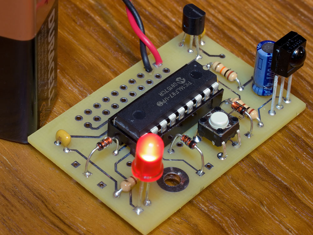
I have an working IR receiver but its tied to some proprietary IR remote sender. it works but I've recently found a commercial DIY style product that uses learning on the receiver side so that you can use ANY remote sender and have various buttons map to the 16 or so pin outputs.
in fact, since its learning you can have buttons or button groups span different source remotes, perhaps one for volume from an old stereo and another for on/off from something else. like that.
before I order a sample kit, I was curious if there are any good ones that people have used before (or created themselves) - and it would be NICE if the source to the pal wasn't locked... all the commercial ones are locked, I think, and so you are stuck if the seller decides not to support to sell more in the future.
here's one I found:
TinyIR2 Learning IR remote control receiver
are there others like that, perhaps ones that are 'open' ?
the learning feature seems to be such a nice thing to have - its what sets this kind of design apart from all the other 'easy' ones. I'd like to stay with a learning receiver and not have to do the learning on the sender side.
TIA,


