Well, nobody
else around here seems to like the idea of using USB voltage to power an amp, because they're all glass-half-empty naysayers
, but I for one happen to think it's a spiffy idea.
Quote:
Originally Posted by joneeboi /img/forum/go_quote.gif
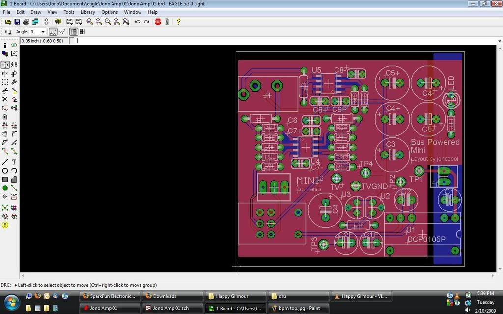
Something I noticed immediately after posting the pictures is that I can probably connect the virtual ground to the USB ground. The output voltage is isolated, so it float to whatever voltage no problem while I clamp down the virtual ground. That way the whole bottom can be routed as a ground plane and connected to the casing, much like the Mini^3. That should be okay, right?
|
If I understand the science correctly, that's a bad idea, and the two grounds should remain fully isolated to avoid ground loops and other less pleasant events.
Quote:
| Also, I can probably snake my way from the USB power input at the back to the front for a board-mounted LED like the Mini^3. It's only drawing a couple mA, but I figure it'd be best to save the precious boosted power for the amplifier itself. |
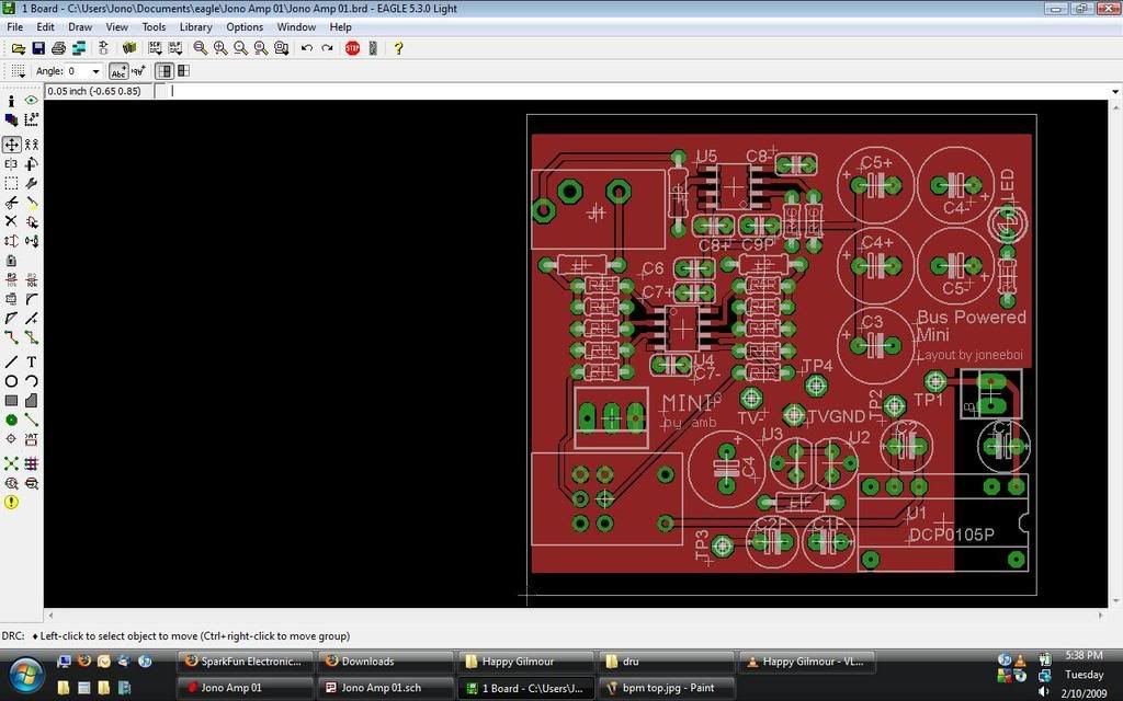
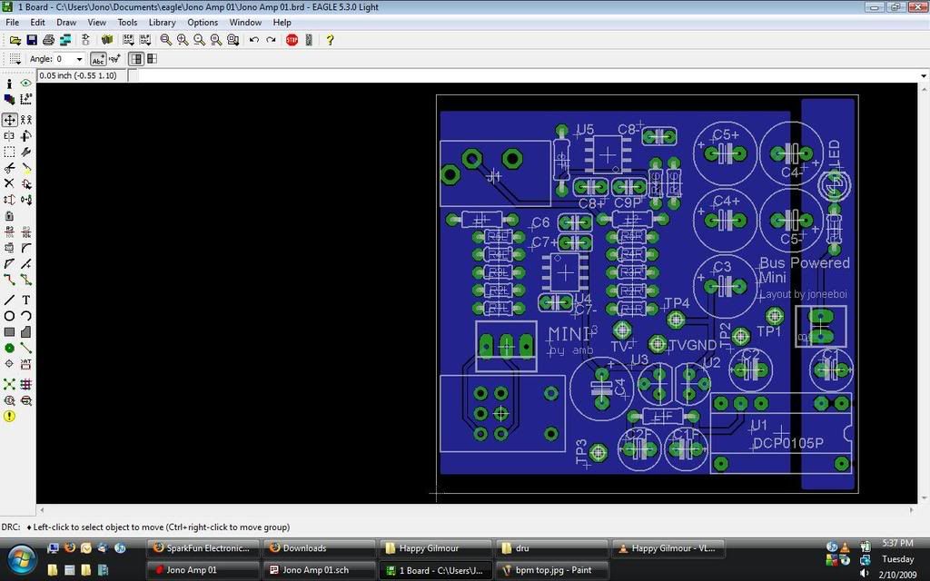
I personally would put the LED on the isolated, boosted end of the DCP, as that way it tells you not that your computer is supplying voltage to the USB port, but that the power converter is working as it should, and hasn't gone into shutdown for whatever reason (overtemperature and undervoltage for sure; I'm not sure how it handles overcurrent.)
Quote:
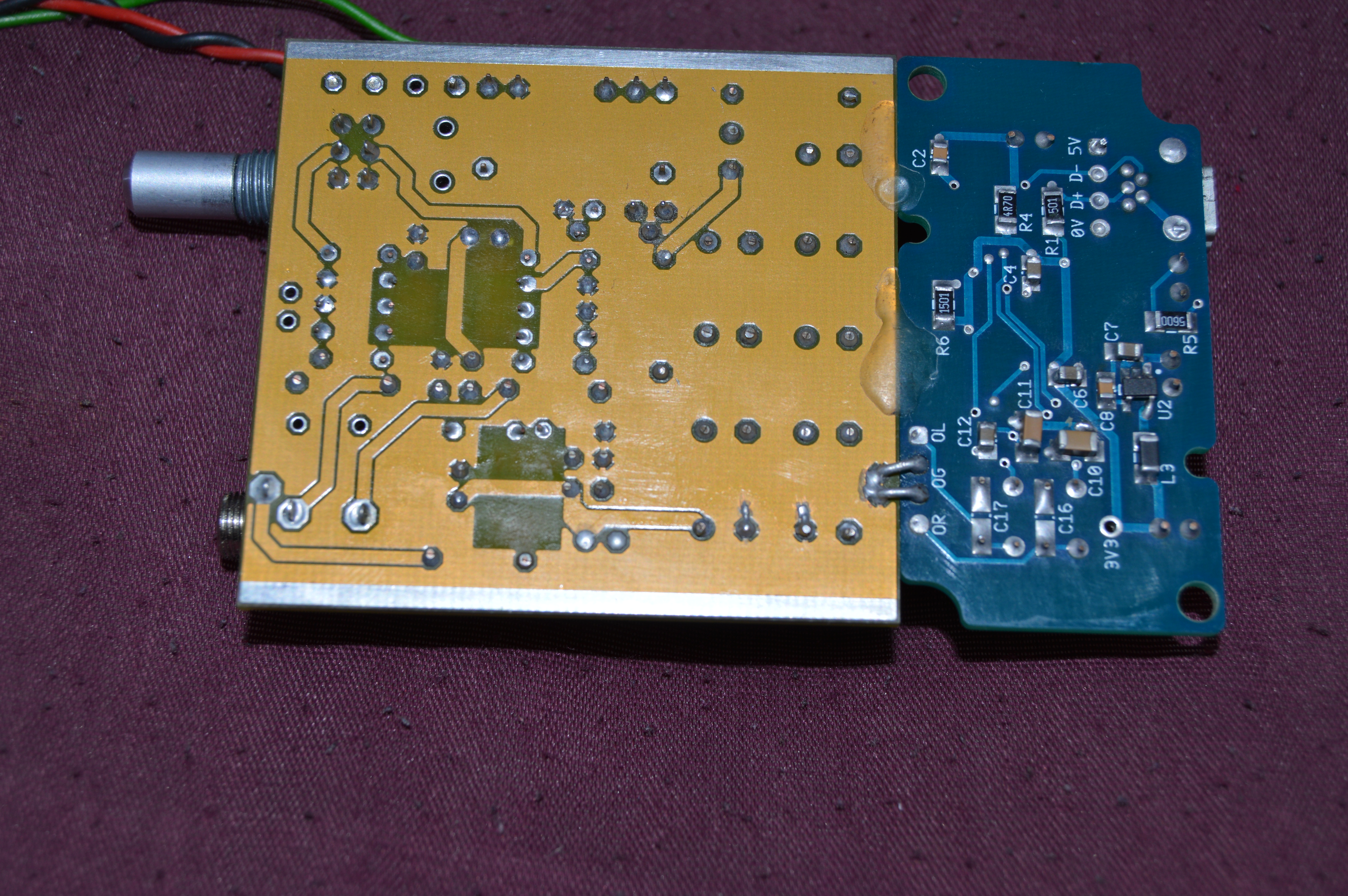
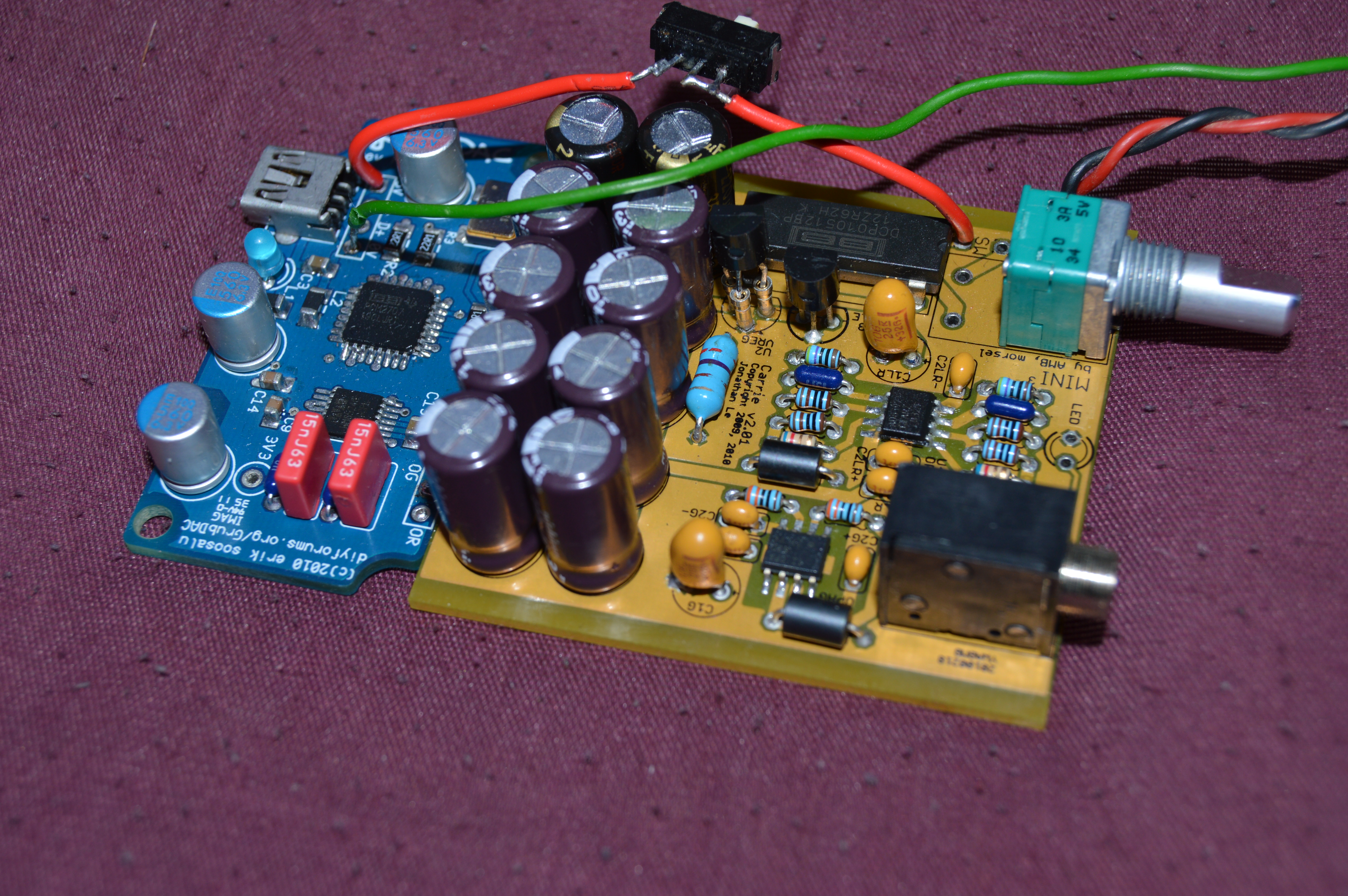
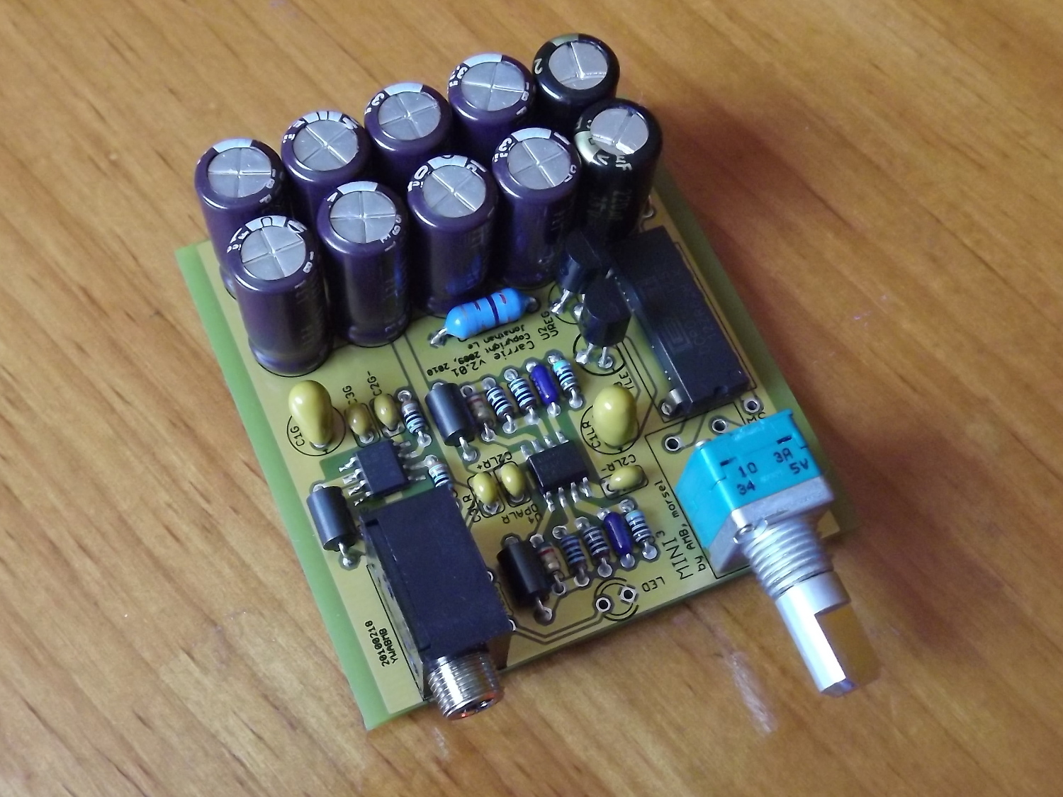
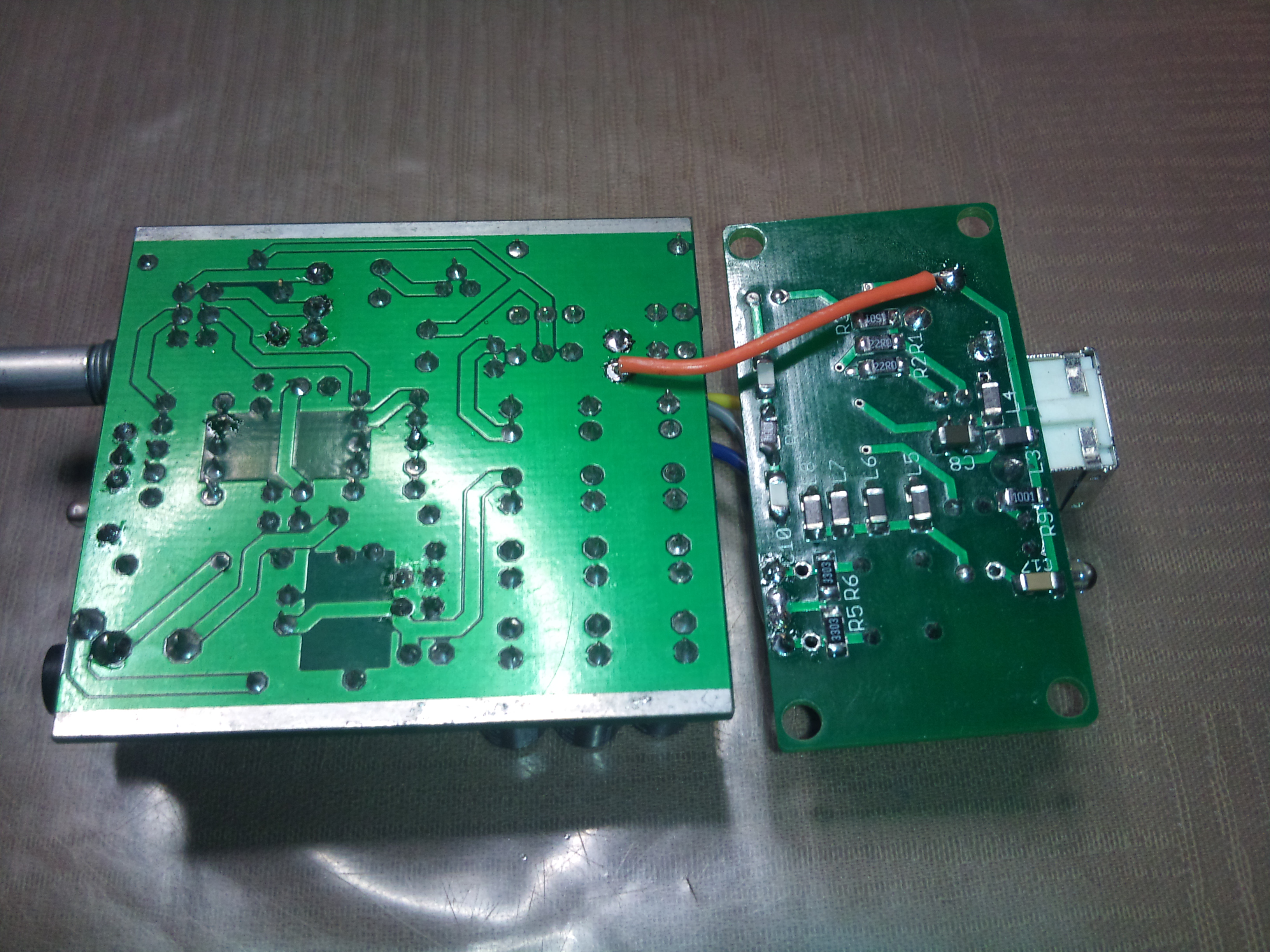
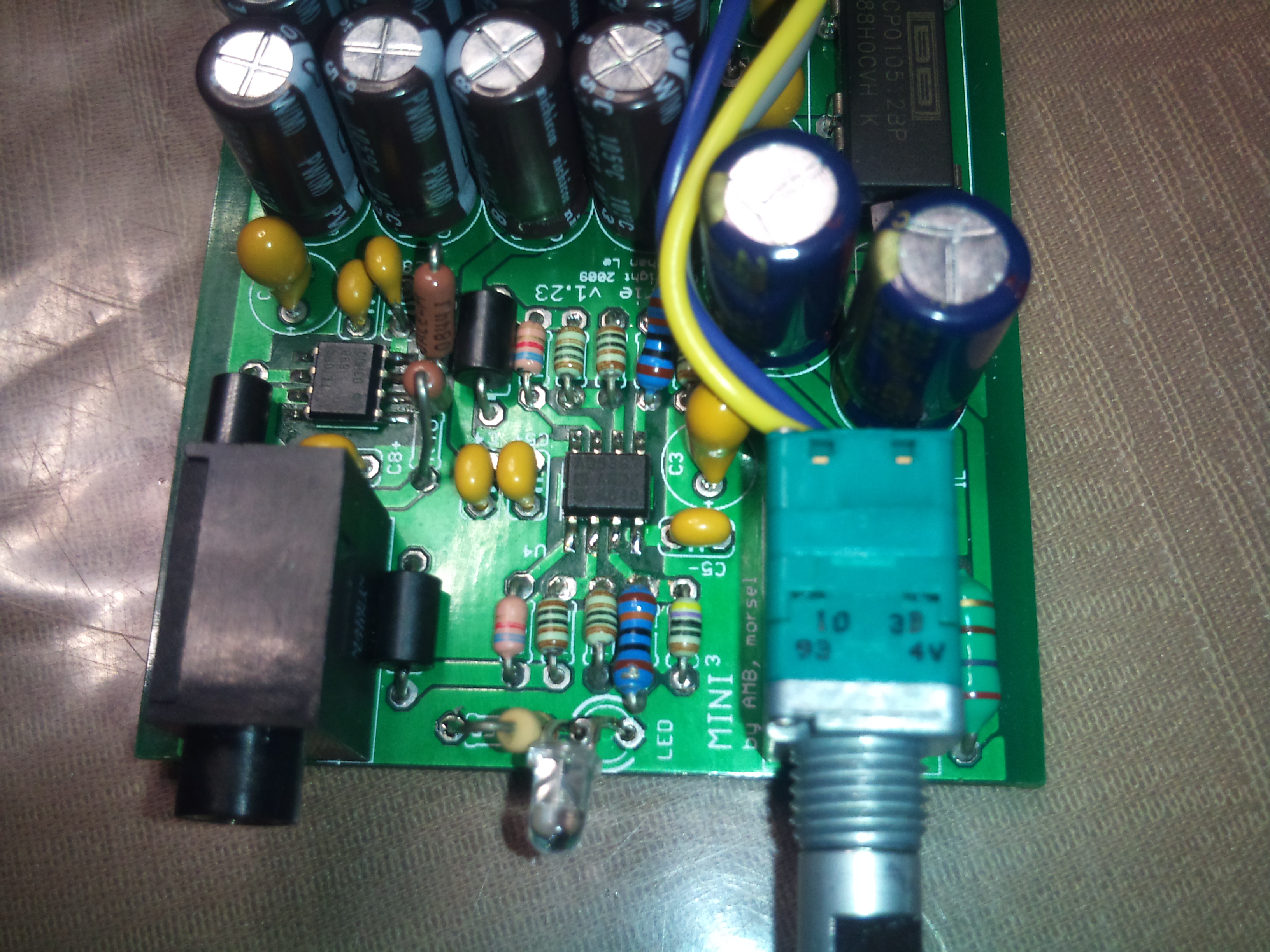
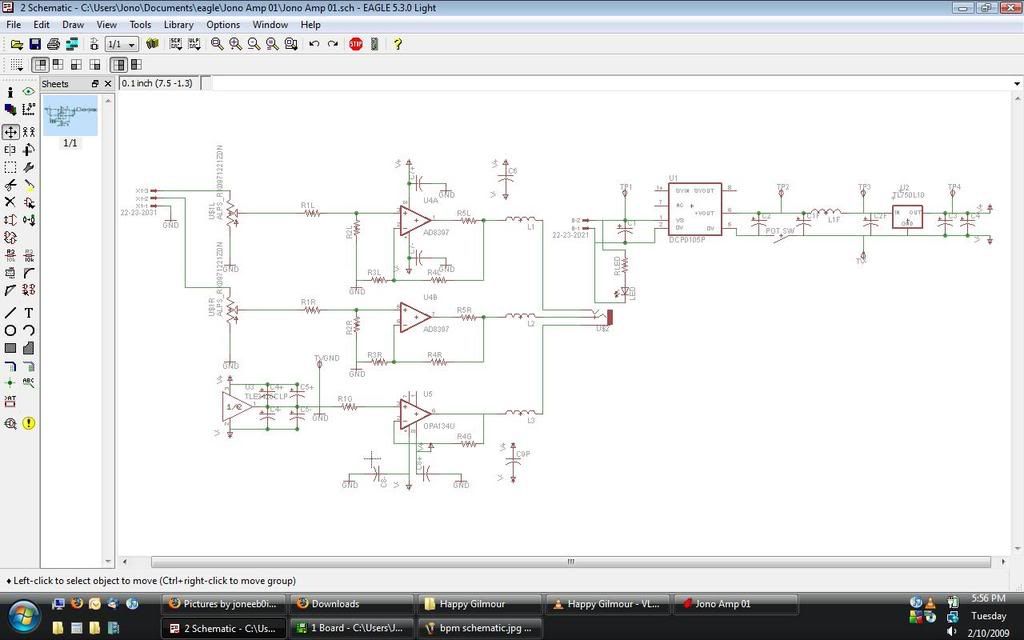
| There are lots of capacitors in the power supply just because there's room. I wonder about the inrush current of having all those capacitors. I might even be able to make them bigger speccing them for a lower voltage. For instance, the electrolytic C4+, C4-, C5+ and C5- only see half the regulated 10V, but I specced it for 16V in case of some sort of fault. It uses the same 470uF caps as the Mini^3. As you can see, I borrowed quite a bit from amb's design. |
That could be an issue; I'm not real clear how the DCP chips handle peak current draw. What are you using for C1 - 2,2uf, like in the datasheet? I wonder if adding a much larger cap in parallel with that, and moving the power switch to be in front of the DCP, would help; wouldn't the 5V reservoir cap, basically, then see at least part of the start-up current rush?
Quote:
| Thoughts? I think better when I do it out loud, so it helps when I can discuss with people. I have lots of little things to clean up, but I just wanted to get some of the technical stuff down pat now before it's too late. My biggest fear so far is about the isolated voltage somehow becoming +/- 5V relative to USB ground with the use of the TLE. That's what happens when you use an isolated DC booster, right? |
I think it's a nice idea - I came up with an identical power design a day or two ago, not having seen this thread before. Have you considered skipping the TLE entirely, and using one of the split-voltage DCP chips? The DCP0112DP, I think it is, is 5V in, fully isolated +/-12V out. It'd simplify things a tiny bit, IMO. Otherwise, you should be fine so long as the USB ground never connects to anything on the "other side" of the isolator - +V and 0V in, and +V and 0V out, but the two 0V terminals shouldn't connect, otherwise you're defeating the whole purpose of the isolator... I think.