rds
Headphoneus Supremus
- Joined
- May 4, 2008
- Posts
- 2,045
- Likes
- 31
I wasn't able to find a mods thread for this card anywhere and this card can be really nice with a few basic mods. So I've taken some time to figure out what is what on this card in terms of the stereo output stage.
Note: Everything on this card is surface mount and the board is very cheap. This requires some soldering skills if you want to be able to use the card again

I don't think this is good beginner project.
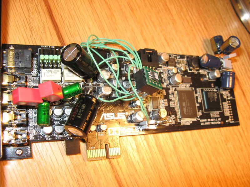
Final Modded Card:
Mod 1: Quality coupling caps
I chose to go with 22uF (same value as stock/CS4398 datasheet) 25V Nichicon Muse ES bypassed with 0.22uF Wima mkp.
[FYI All the stock electrolytic caps appear to be 10V.]
These are the left and right front coupling caps:
Apply heat to the edges of the solder pad and gently pull these off one side at a time (there are 2 solder pads).
I should say now, keep your soldering iron on low temp. I used 250C - this is as high as you should go.
Add a little solder to the pads.
Add the caps of your choice.
In the photo above these are the dark purple (black gate nx-hiq) caps.
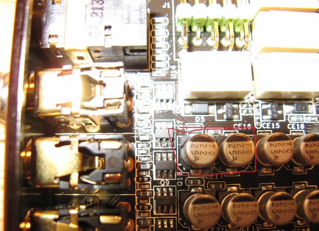
Mod 2: Quality Low Pass Caps
this is a low pass filter. It is probably meant to remove high frequency noise. So this cap mod replaces the cap that is forming the low-pass filter
I used the same method to remove these caps as done in for mod 1. I used 220 uF (same value as stock) 25V Nichicon Muse KW (from Mouser). The replaced caps are the little gold and black ones closest to the purple black gates.
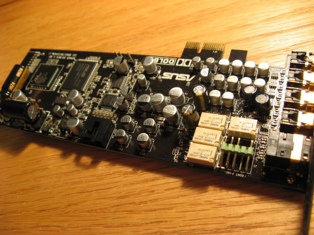
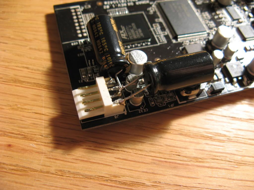
Mod 3 ower supply decoupling caps
Also Nichicon ultra low esr HZ 1200uF caps decoupling the power supplies as seen in the second picture. Make sure to arrange the polarity as shown and use caps rated at at least 16V.
Mod 4: Upgrade Op-amp (yikes!)
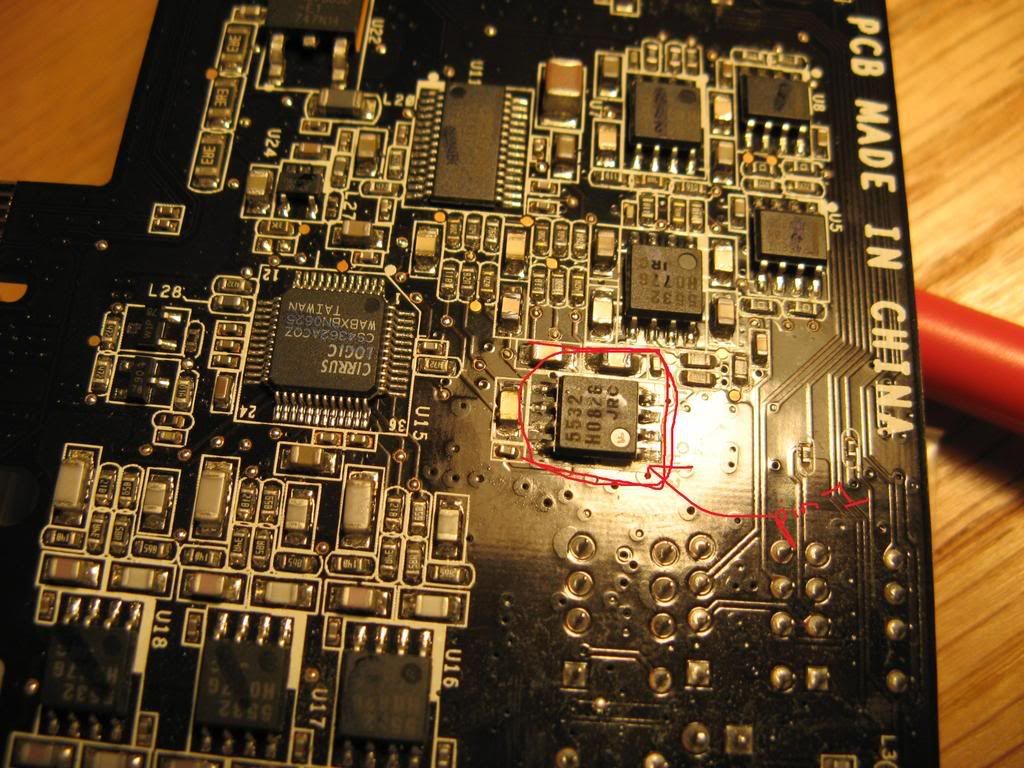
Note: The opamp I have circled is definitely the cs4398 DAC opamp, but I haven't gone through the painstaking process of determining whether there is another opamp before the output. I don't think there is.
Now I also decided to replace the opamp. You should think twice about this if you're not familiar with how to do this. Basically you want to heat all pins on one side of the opamp and while the solder is liquid lift that side from the board. Then do the same with the other side. It's a little tricky to desolder these chips, so if you can practice on an old motherboard or something you should.
Have fun!
Note: Everything on this card is surface mount and the board is very cheap. This requires some soldering skills if you want to be able to use the card again
I don't think this is good beginner project.
Final Modded Card:
Mod 1: Quality coupling caps
I chose to go with 22uF (same value as stock/CS4398 datasheet) 25V Nichicon Muse ES bypassed with 0.22uF Wima mkp.
[FYI All the stock electrolytic caps appear to be 10V.]
These are the left and right front coupling caps:
Apply heat to the edges of the solder pad and gently pull these off one side at a time (there are 2 solder pads).
I should say now, keep your soldering iron on low temp. I used 250C - this is as high as you should go.
Add a little solder to the pads.
Add the caps of your choice.
In the photo above these are the dark purple (black gate nx-hiq) caps.
Mod 2: Quality Low Pass Caps
this is a low pass filter. It is probably meant to remove high frequency noise. So this cap mod replaces the cap that is forming the low-pass filter
I used the same method to remove these caps as done in for mod 1. I used 220 uF (same value as stock) 25V Nichicon Muse KW (from Mouser). The replaced caps are the little gold and black ones closest to the purple black gates.
Mod 3
ower supply decoupling capsAlso Nichicon ultra low esr HZ 1200uF caps decoupling the power supplies as seen in the second picture. Make sure to arrange the polarity as shown and use caps rated at at least 16V.
Mod 4: Upgrade Op-amp (yikes!)
Note: The opamp I have circled is definitely the cs4398 DAC opamp, but I haven't gone through the painstaking process of determining whether there is another opamp before the output. I don't think there is.
Now I also decided to replace the opamp. You should think twice about this if you're not familiar with how to do this. Basically you want to heat all pins on one side of the opamp and while the solder is liquid lift that side from the board. Then do the same with the other side. It's a little tricky to desolder these chips, so if you can practice on an old motherboard or something you should.
Have fun!