Millett "Starving Student" hybrid amp
Jul 14, 2008 at 11:38 AM Post #616 of 7,277
Quote:

Originally Posted by V-DiV /img/forum/go_quote.gif
I've just finished my summer commuting and will have some time for a project in the near term. I can't wait any longer for the SOHA II so I'm going to build a Starving Student. I watched this thread when it first started but haven't followed it for a while and I don't necessarily want to read all 600+ posts. Are there any consensus good-bang-for-the-buck upgrades/replacements to the standard BOM listed on Pete Millett's website?

Thanks,
Vic


Change the size of the electrolytic caps to 470uf. 470uf for the caps in the back help tame the startup stutter of the VOIP power supply, while 470uf up front shoves the bass filtering down to ~10Hz for low impedance cans (Grados).
 
Jul 14, 2008 at 9:04 PM Post #617 of 7,277
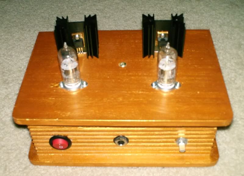
For those of you waiting for PCBs, the next stage has been completed. Still no real ETA, but it is getting closer. The basic holdup right now is trying to figure out a decent heatsink strategy. In mine, I connected the mosfets to the case and added a largish sink. This barely even gets warm, so it is probably a little bit of overkill. This sort of construction might require a little more work for some, but it does allow just using a metal sheet as the top with a sink bolted on -- I used the Hammond case as it was sitting in a box of junk on the floor, but it is not a necessary expense. This style of construction also keeps the voltages inside the chassis, which is a good thing. 48V is probably not particularly dangerous, but it is enough to remind you that you are playing with electricity.

SS1.jpg


SS2.jpg
 
Jul 14, 2008 at 10:12 PM Post #619 of 7,277
Quote:

Originally Posted by tomb /img/forum/go_quote.gif
Where did you get it?


In the drawer of heatsinks I have ... I think it probably came from Nebraska Surplus. They seem to have more and anything on that page would be fine. I think CPU sinks would work, too, for those that have old computers sitting around that they can strip parts from. I'll also try just removing the sink and see how well the case works on it's own.

One other thing worth noting, I used the cheapest caps that were 470u/63V/105 degrees I could find, and the cheapest resistors. I also used IRF610's as I have a drawer full of them. These things made little difference. Cheap is good for this project.
 
Jul 14, 2008 at 11:40 PM Post #620 of 7,277
Quote:

Originally Posted by tomb /img/forum/go_quote.gif
Change the size of the electrolytic caps to 470uf. 470uf for the caps in the back help tame the startup stutter of the VOIP power supply, while 470uf up front shoves the bass filtering down to ~10Hz for low impedance cans (Grados).


Thanks TomB. I gathered that much from the Aussie group buy thread. I had wondered if there were any easy swaps for an upscale part that would make a big difference, but I'll follow dsavitsk's advice that "cheap is good" for this project.

Cheers,
Vic
 
Jul 15, 2008 at 1:25 AM Post #621 of 7,277
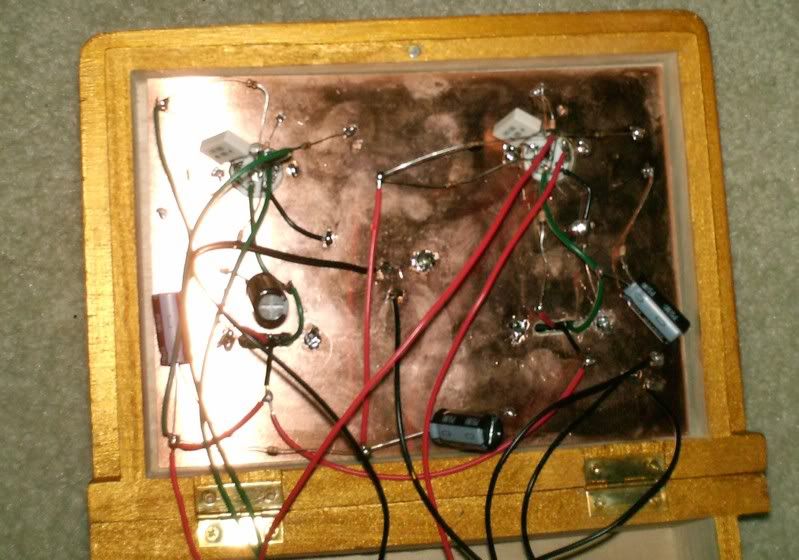
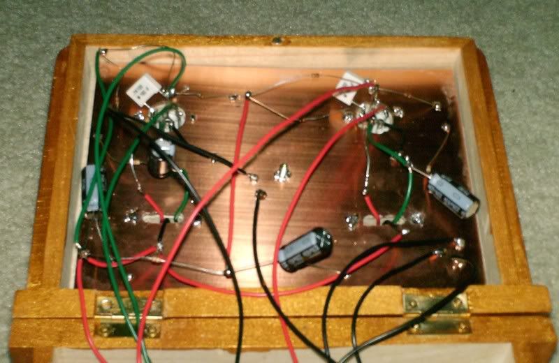
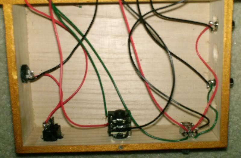
Hey Guys, Here are some early pics.
I do have a problem because it doesn't work. If anyone can look at the pics and help me, I would appreciate it! The left seems to be grounded (even at the pot), so please help me!
HPIM1434.jpg

HPIM1437.jpg

HPIM1438.jpg

HPIM1439.jpg

Thank You in advance!
 
Jul 15, 2008 at 2:23 AM Post #622 of 7,277
We need more info. Does it do anything? Tubes light up? Smoke? Fire?

Did you use insulating washers on the FETs? I can't tell from the pictures, but that'd be an easy thing to go wrong that I think would muck up the works. Heck, even if you did I'd check continuity with a DMM to be sure.

And another one to check make sure that you have the power supply jack wired correctly, I've certainly been known to use the wrong tab on those switched jacks.

Also, I'd swear from looking at those pictures that you have the headphone jack wired wrong. Again, it's a little hard to see in the blurry pics but I just compared it to one of my amps that's sitting here and it sure doesn't look right.

Otherwise, have you retraced the circuit with the schematic near by. It took me 5 times through mine to find the mistake that I made when I built mine.
 
Jul 15, 2008 at 2:29 AM Post #623 of 7,277
Quote:

Originally Posted by -=Germania=- /img/forum/go_quote.gif
Hey Guys, Here are some early pics.
I do have a problem because it doesn't work.


It's hard to tell from the pics. But, a first step might be to work on the grounding. Pick a point and connect all the ground leads (input, output, pot, Rk, bottom of the heater, ps caps, power input, etc.) to that point. Beside the fact that this will cut down on noise once you get it going, it will also let us see a little better that things that should be grounded are, and things that shouldn't be, aren't.
 
Jul 15, 2008 at 4:06 AM Post #624 of 7,277
Quote:

Originally Posted by n_maher /img/forum/go_quote.gif

Also, I'd swear from looking at those pictures that you have the headphone jack wired wrong. Again, it's a little hard to see in the blurry pics but I just compared it to one of my amps that's sitting here and it sure doesn't look right..


X2 That was my first thought. Looks like you wired the switched side of the jack thus breaking the circuit when you plug the headphones in.
 
Jul 15, 2008 at 3:48 PM Post #626 of 7,277
Ok, time to fess up... caveat: I am NOT a machinist, and did all this with my Dremel, drill press and hand drill (stepped drill bit). The front panel was material left over from a Pars Metal case.

Parts
Case
Ground Plane
Front
Guts
Guts 2
Top

Yes, balanced. I finished late last night, and decided to delay power up until tonight, since I wouldn't sleep otherwise - successful or not. The fancy parts were left over (Neutriks, Vampire XLR, ALPS stepped, Kimber RCA). Everything else was ~$100.
 
Jul 15, 2008 at 4:33 PM Post #629 of 7,277
Well, if the inside pin is the power and the outside is ground, then the jack is wired correctly.

I think that the problem is that the plastic washer is on the wrong side and I used the metal one where the plastic should be. That would be a reason for it to have no power to the tubes. I realized the headphone jack issue as soon as I posted the pics. I just need to fix those problems and test again, going through the whole thing with a multimeter.

I am sorry for the low quality of the pics and how bad it looks in the pics. In person it is a very shiny gold and I am going to paint it up more once I get it built (crackle finish? or some other design. I promise that it will look very interesting and the two headphones stands I made also match the AMP (check out in the headphone stand thread).
 
Jul 15, 2008 at 5:32 PM Post #630 of 7,277
Quote:

Originally Posted by -=Germania=- /img/forum/go_quote.gif
Well, if the inside pin is the power and the outside is ground, then the jack is wired correctly.


Which jack? The DC power jack? I'd hope that if you didn't know whether or not you had it wired correctly you'd just pull out your DMM and check it with power applied (but not attached to the circuit). I inherently don't trust wallwarts so I always check their polarity, it's just good practice.
Quote:

I think that the problem is that the plastic washer is on the wrong side and I used the metal one where the plastic should be.


You need to explain things better, or at least more completely. I'm pretty sure here that you're talking about the FETs and the isolating washers but I'm guessing and guessing makes me not want to help for fear of just wasting my time.
 

Users who are viewing this thread

Back
Top