The Stax thread (New)
Status
Not open for further replies.
Jul 18, 2013 at 4:23 PM Post #23,641 of 24,807
I actually talked to someone who's been using his Japanese transformer in America for at least a year and he said there are actually linear regulators that keep the voltage at 12V, even though the input voltage is greater than that.


If anyone with the knowledge of the inner parts of the Amp and the power supply of the 252s can confirm this then that would be great.  

I see that Elusive Disc's description of the 2170 specifically warn of doing this though, saying it can damage the amp and the headphones...

I'll see if he can hop on here and confirm. He knows much more than me. He probably also has a picture of the PCB...

@M-15: the yen has been weak like this for the past few months :wink:
 
Jul 18, 2013 at 4:27 PM Post #23,643 of 24,807
Wow so all of this "you can't use it with American voltages" stuff actually hasn't been tested by people here and you're just blindly suggesting things? o.0

What do y'all use then?

Either they're not from America, or probably paid full retail price...
Or they have a better amp. :rolleyes:
 
Jul 18, 2013 at 5:30 PM Post #23,644 of 24,807
Quote:
@M-15: the yen has been weak like this for the past few months
wink.gif

Oh I know. I keep up with my currency markets. I only ask because the currency easing by the BOJ seems more of a permanent norm now. I realize Stax won't flucate their MSRP based on small movements, but the value of the Yen is nothing like it was before and done purposefully by the BOJ and they intend to keep it at current rates. Price Japan is flooded with SR-009 orders now. Just wondering when Stax will adjust to the new norm.
 
Jul 18, 2013 at 6:36 PM Post #23,646 of 24,807
Don't kid yourself.  Stax is building the 009 24/7 and there isn't stock anywhere in the world, not just Japan.  Stax also has no incentive to make less in other markets when they can't keep stock on the shelves.  If a day comes that they are sitting on hundreds of unsold units, then they might have incentive to drop their wholesale price.
 
Jul 18, 2013 at 7:44 PM Post #23,647 of 24,807
Voltage in my country is 230 volts. So, would 220 or 240 be best for amp and headphones?
 
Jul 18, 2013 at 8:19 PM Post #23,648 of 24,807
Quote:
 
Do a diode test on the transistors as I'm pretty sure some of them are fubar.  You can also measure voltages between the channels, especially before the output caps.  If they aren't close to each other then something is very wrong. 
 
No chance in hell to find any replacement sand though. 

OK thanks, I will do those tests once I get a replacement dmm in, would the bias and offset trimpot adjustment have anything to do with no left channel sound? 
 
I'm just a bit afraid one of the high 600v b+ points will pop my dmm again. 
 
Quote:
Wow so all of this "you can't use it with American voltages" stuff actually hasn't been tested by people here and you're just blindly suggesting things? o.0
 
What do y'all use then?

I'm still sticking by my recommendation as a single poster made a thread regarding running there 100v Stax on the mains and half the amp ended up popping fuses due to the state they were in the States the mains fluctuated more then the 125v rated fuse can handle. KG and Spritzer has already chimed in and said it's best to stick to the right voltage step down trafo or replacing the wallwart completely. Don't say you weren't warned.
Quote:
Voltage in my country is 230 volts. So, would 220 or 240 be best for amp and headphones?

Adjust for 240v this way the trafo/amp runs cooler with the less than 10v requirement on the AC. 230/240 is used in Europe and Australia. 220v is used in Korea.
 
Jul 18, 2013 at 8:19 PM Post #23,649 of 24,807
I've got a quick question.
I brought my SRD-X pro to the airport, and it seems to have a noise problem.

The noise sounds just like the noise one would expect from an integrated DAC, so I think it's just electrical interference.
Putting my hand over it stops the noise as well, and the noise really varies with where I put it.

It's also on battery, and the noise happens only when turned on, and even with no input.

Am I right to think this is from the crowded EM filed environment at the airport, and that something didn't suddenly go wrong?
 
Jul 18, 2013 at 8:22 PM Post #23,650 of 24,807
RFI and EMI comes to mind. Probably just mean's some of the area's in the SRD-X is not shielded/properly against mentioned interference to the amp. Not to mention, an airport with thousands of radio/electrical waves on various frequencies flowing through the air.
 
Jul 18, 2013 at 8:23 PM Post #23,651 of 24,807
Quote:
Don't kid yourself.  Stax is building the 009 24/7 and there isn't stock anywhere in the world, not just Japan.  Stax also has no incentive to make less in other markets when they can't keep stock on the shelves.  If a day comes that they are sitting on hundreds of unsold units, then they might have incentive to drop their wholesale price.


And this is the truth, ladies and gents.
 
Jul 18, 2013 at 11:00 PM Post #23,654 of 24,807
you can endlessly Wonder whats wrong which is the best way to go it seems or you can just test the transistors its AB easy...
 
Jul 18, 2013 at 11:27 PM Post #23,655 of 24,807
Quote:
you can endlessly Wonder whats wrong which is the best way to go it seems or you can just test the transistors its AB easy...

That's exactly what I'm going to do today. Since my DMM is borked and a replacement on it's way early next week. I'm going to do two things to identify damage and rule out whatever components is borked.
 
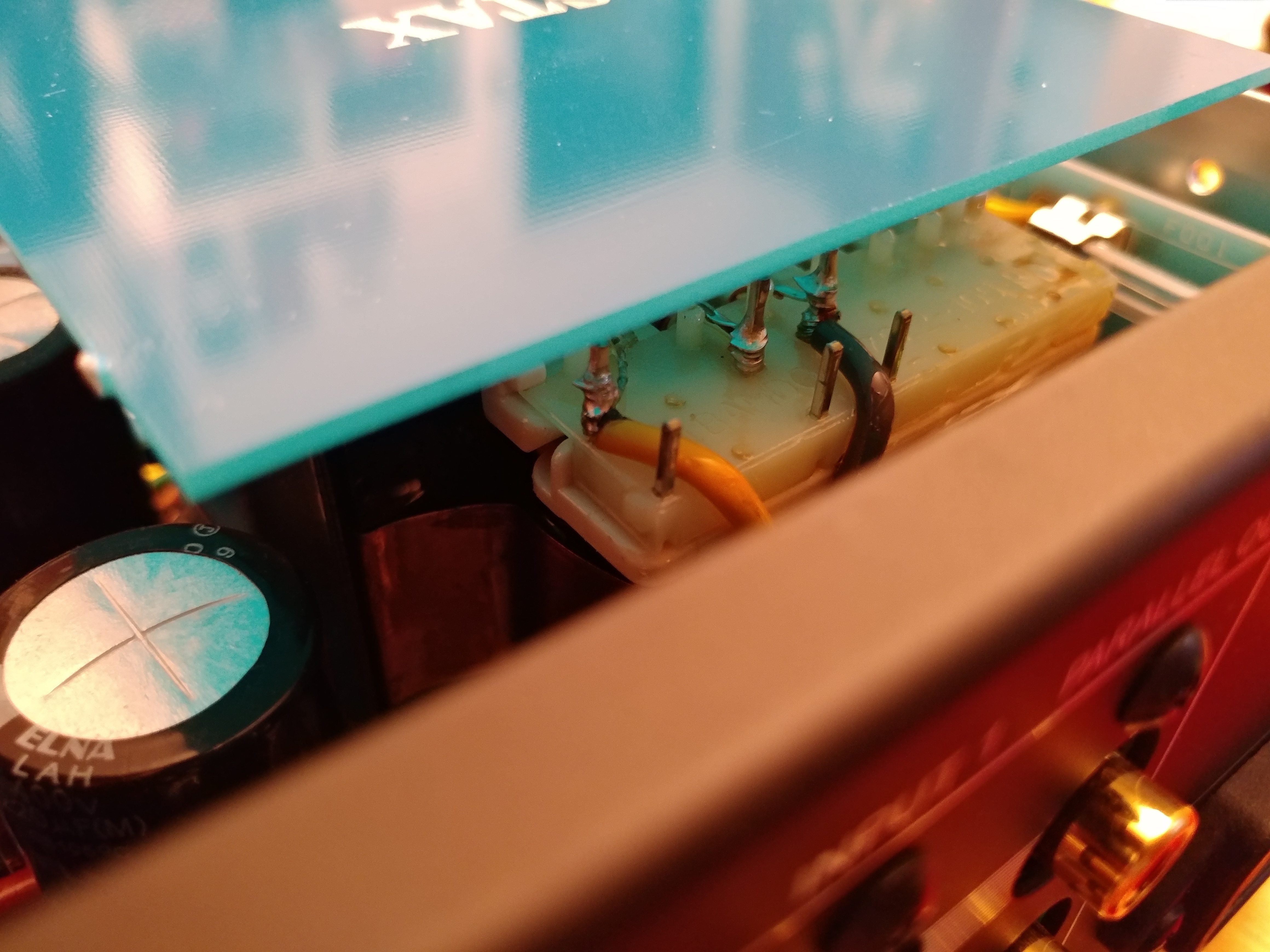
Originally I said the two ELNA 350v caps I measured (assuming one for each channel) one of the cap's measured 315vdc on the neg pole and 620 on the positive pole while the other ELNA cap measure 315vdc and 0vdc respectively, thanks to spritzers "replace/measure diodes in the output stage" idea, I looked at the PCB more carefully following the tracings from the R/L-input to the trafo ps and what looks like (assuming) is the output stage 4 diodes with bypassed ceramic film caps and 2 ELNA caps, the white bias 600v B+ wire connects to the 4 transistors and copper bridge comes from this section.
 
Now I'm going to first de-solder the 4 diodes in that output stage (?) and record the values down and see if I can get replacements if required. Next I'm going to resolder the pairs of the diodes and swap positions with the other two. This way, if the right channel is dead but the left channel is ok, this should give me 315/620vdc on the neg/pos poles of the ELNA caps respectively. And the right channel should read 0vdc on the pos pole with no sound.
 
This is one theory I have of what has happened.
 
The next option is to desolder the 4 big transistors and again swap a pair in for the other pairs position so just swapping places. I'll do it in in steps so if one thing goes kaputz once I turn it on I can narrow this down as a suspect and confirm my findings once I get the DMM in by measuring the points.
 
So it's pretty much a pair of transistors for each channel, pair of offset/balance trimpot adjustment for each channel, output stage has a pair of diodes (used to rectify AC to DC) bypassed by some ceramic film caps running in parallel with two ELNA 350 47uf caps (1 each channel). 
 
If one component was half damaged then I would at least get some static out of the left side through L+/- pins. But the fact that it means there is no sound at all, could only mean dead transistor or diode. Upon close-up inspection nothing looks blown, all solder pads that look half-arsed has been reflowed. If a resistor was blown, my early measurements would've been out of line and physical burnt marks could've been seen. 
 
Status
Not open for further replies.

Users who are viewing this thread

Back
Top