Modifying Millett output
Apr 6, 2006 at 11:15 AM Post #31 of 57
I did the same test point arrangement- with Mouser probe sockets. I got tired of blowing up 5002 buffers
mad.gif


large.jpg


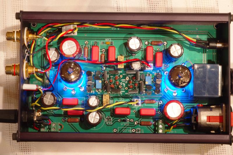
More images here. The probe sockets have worked out well for me. If I ever get around to an acrylic top, I can cut access holes to the trim pots and make it a snap to roll tubes and rebias.
 
Apr 6, 2006 at 11:19 AM Post #32 of 57
Quote:

Originally Posted by NeilR
If you do not have dedicated test point sockets, use one of the ground vias around the edge of the board for your black test probe. It is soooo easy to short the buffer out if you try to use both test points adjacent to each other.


I do not have dedicated points, so I have been doing it just the way you adviced. No problems so far.
biggrin.gif
 
Apr 6, 2006 at 11:27 AM Post #33 of 57
Yes, probe socket = tip jack. I think it's a great idea, and really simplifies the whole process after casing. If you have dual inputs on your meter, you can even measure them simultaneously, which is nice.

Good looking amp, Neil. Got your screws fixed and everything.
smily_headphones1.gif


Mine still sits on a board for now
rolleyes.gif

voodoo_rig4.jpg
 
Apr 6, 2006 at 11:33 AM Post #34 of 57
I have a couple of spare boards and I've been thinking about educational uses for them. Here are a couple of ideas:

1) A "Minimal Millet". Build two more. Populate both with just the bare minimum of components needed to make noise. Then slowly add in the stock parts on the 2nd build, one part at a time, comparing the minimum millet (left minimal) to the work in progress to my stock Millet.

2) Remove the film caps. there have been a couple threads discussing the pros and cons to multiple bypass configurations. It would be interesting to try this out and see if the "smearing" is audible to my ears.

3) A High Voltage Millet. Push the envelope on the right side of the tube curves to see if there are measurable or audible improvements. Some of the tube charts seem to be much more linear at 25-30V on the plate. The problem here is that some traces would have to be cut and a separate filament supply added. At that point it starts going beyond the scope of the concept, but might be fun to try out should a surplus of Treads turn up in my parts bin. And why stop there, someone recently suggested a bipolar supply for the diamond buffers. That would require 4 treads (or equivilent) to power the thing
eggosmile.gif
 
Apr 6, 2006 at 11:39 AM Post #35 of 57
Voodoochile,

Nice looking slab! Now I understand your previous comment about doing it the way Pete did his.

I ditched the washers behind the socket head screws. They stuck out past the edge of the case and I thought it looks better without. A better way to do it would be to find washers with the diameter of #4, but with #6 holes in the center. That would be perfect for the Hammond panel.
 
Apr 6, 2006 at 4:54 PM Post #36 of 57
Quote:

Originally Posted by NeilR
2) Remove the film caps. there have been a couple threads discussing the pros and cons to multiple bypass configurations. It would be interesting to try this out and see if the "smearing" is audible to my ears.


DO IT!!!111 it only takes a couple minuites. i reccomend only leaving the films across the "buffer's caps"
Quote:

3) A High Voltage Millet. Push the envelope on the right side of the tube curves to see if there are measurable or audible improvements. Some of the tube charts seem to be much more linear at 25-30V on the plate. The problem here is that some traces would have to be cut and a separate filament supply added. At that point it starts going beyond the scope of the concept, but might be fun to try out should a surplus of Treads turn up in my parts bin. And why stop there, someone recently suggested a bipolar supply for the diamond buffers. That would require 4 treads (or equivilent) to power the thing
eggosmile.gif


try the "higher" voltage. i think im going to buy my next psu with this in mind. i think you could get away with just wiring a small resistor in between teh 2 tubes heaters. this may require, as you say some "creative wiring" but, eeh, its all good fun.

as far as a "dual suply," see my thread about 4 threads down.... millet with no output cap.millet hybrid reference
 
Apr 6, 2006 at 6:08 PM Post #37 of 57
Quote:

Mine still sits on a board for now


I would never case that up Mark.looks way cool just as it is.If anything maybe some sort of handles on the sides or tall ones front to back just to make moving it around easy but case up up ?

[size=small]DON'T DO IT MAN ![/size]

Quote:

the output resistor is totally optional.


Quote:

I used the 1/4 watt VD resistors spec'd in the various BOMs. I didn't consider the issue when I ordered my parts. If I make another I will upgrade that part. Good point.


If added should be the best you can get since everything will go through and so can be considered a "Choke point".The wattage ? Isn't this amp in the 1W output range ?
If yes then 2 Watts would be a nice margin for safety

Quote:

I'm all for the great sound instead of great measurements and this little amp seems to underline that point.


funny how some amps are beneath the radar then all of a sudden popular proving sound has very little to do with popularity.Mark built his two years before the recent mass builds and posted the pictures and his impresssions of the amp yet it was so not commented on,was so overlooked as an amp of contention the thread lasted maybe a day before dissapearing to page 2 then on to oblivion.Now it is all over the internet and headroom has a version being sold commercially.Weird how that goes.

Quote:

And as for hot-plugging headphones with either the HA3-5002 or diamond buffer module in general, if you're reasonably careful, then it should not matter anyway. I've never blown any buffers of either flavor with my PPAs. Just have to pay attention when plugging and unplugging.


should be a sticky thread on adding a "output mute" switch to every headphone amp no matter the topology with the threat that if you do not use it before plugging/unplugging and powering/powering down you lose your rights to post at headfi
very_evil_smiley.gif


Quote:

As for the test points, I have some tip jacks I plan to install in the back panel if I ever case my millet. On the first one I built a few years ago, I added header pins, and then made a little adapter from a motherboard LED plug to fit it, with a pair of alligator clips on the other end. That worked well for an amp "cased" as Pete did in the original article- wide open.


Pretty standard during the "golden age" of audio to have the bias adjustment and bias probe points brought out to a panel so there was no need to "look under the hood" (very dangerous with high voltage tube gear anyway) to fiddle around with it.In the highest end there was even a panel mounted bias meter but that not essential.Maybe the "ultimate" layout would be a front panel bias adjuster and test probe points ? Would simplify the "tune as you go" process.

BTW-Not you Mark.All "Millett On Board" needs is a couple of these

testcolr.jpg


http://www.keyelco.com/products/prod...CategoryID=111

Quote:

I do not have dedicated points, so I have been doing it just the way you adviced. No problems so far.


BZZZZZZZZZZZZTzzzzzzzzzzzzzZZZZZZZzzzzzzzTTTTTTTTT TTzzzzzz


icon10.gif
 
Apr 6, 2006 at 6:11 PM Post #38 of 57
Quote:

Originally Posted by NeilR
1) A "Minimal Millet". Build two more.

2) Remove the film caps.

3) A High Voltage Millet.


Before doing any of these things, you should replace the cathode bypass caps (the two little electrolytics that are close to the buffers.) The entire audio signal goes through these caps making them as important as the output caps. If it was worth blackgates on the output, it is worth blackgates in this position as well.
 
Apr 6, 2006 at 6:13 PM Post #39 of 57
The SOHA group tried to run down the voltage to the heaters with a resistor and I think they had issues. They evolved into a regulated design. That is a possibility; heat has to be computed.

What exactly did you do to your Millet. It was not clear to me from that thread. You didn't turn it into a two stage cathode follower, did you?


Quote:

Originally Posted by nikongod
DO IT!!!111 it only takes a couple minuites. i reccomend only leaving the films across the "buffer's caps"
try the "higher" voltage. i think im going to buy my next psu with this in mind. i think you could get away with just wiring a small resistor in between teh 2 tubes heaters. this may require, as you say some "creative wiring" but, eeh, its all good fun.

as far as a "dual suply," see my thread about 4 threads down.... millet with no output cap.millet hybrid reference


Apr 6, 2006 at 6:21 PM Post #41 of 57
Quote:

Originally Posted by rickcr42
BTW-Not you Mark.All "Millett On Board" needs is a couple of these

[IMG

http://www.keyelco.com/images/products/testcolr.jpg[/IMG]

http://www.keyelco.com/products/prod...CategoryID=111


BZZZZZZZZZZZZTzzzzzzzzzzzzzZZZZZZZzzzzzzzTTTTTTTTT TTzzzzzz


icon10.gif


Rick, they look like the keystone test points that Tangent lists on his Steps and Tread BOMs. The keystones do not fit. I tried. I guess you could cut one prong off, maybe. Even if they can be made to fit, it would not be a good idea to install or use the ground test point due to the close proximity to the hot point, as I mentioned above.
 
Apr 6, 2006 at 6:26 PM Post #42 of 57
Quote:

Originally Posted by dsavitsk
Before doing any of these things, you should replace the cathode bypass caps (the two little electrolytics that are close to the buffers.) The entire audio signal goes through these caps making them as important as the output caps. If it was worth blackgates on the output, it is worth blackgates in this position as well.


If I were going to mod that board, I would make C2 the same size as the other caps. I think that was a strategical error. I agree with you- they are just as important [just as much in the signal path] as the output couplers. I hate to ruin the aesthetics with some big caps air wired onto the board, but I guess it ought to be done. I've been thinking about that for the "educational builds". All I used for C7 was a Cerafine. I'm haven't gotten into boutique caps [yet].
 
Apr 6, 2006 at 6:40 PM Post #43 of 57
Quote:

The keystones do not fit. I tried. I guess you could cut one prong off, maybe. Even if they can be made to fit, it would not be a good idea to install or use the ground test point due to the close proximity to the hot point, as I mentioned above.


Check the rest of the Keystone catalog.There are so many pcb mount options from available them that if not there it likely is not availabvle anywhere ! (have you considerd a simple hard metal "hook" type post ?)

Good company with great service,unique parts and great prices.One of the true DIY Supply good guys
 
Apr 6, 2006 at 6:41 PM Post #45 of 57
Quote:

Originally Posted by NeilR
If I were going to mod that board, I would make C2 the same size as the other caps.


You are probably correct. However, BG 220uF/16V STD fit fine.

Quote:

All I used for C7 was a Cerafine. I'm haven't gotten into boutique caps [yet].


Oops, from the red jackets they looked like N series in the pics. Now that I look again, I see they are cerafine. Well, I think the cerafines are of fine quality, and I doubt you would hear much difference moving from them to BG in this application. But I'd put some cerafines (or the BG std's) in C2 nonetheless.
 

Users who are viewing this thread

Back
Top