I'm having start-up problems. And as per AMB's website I've been through and looked for cold joints/short circuits as best I can and I've re-soldered a few points just to make sure.
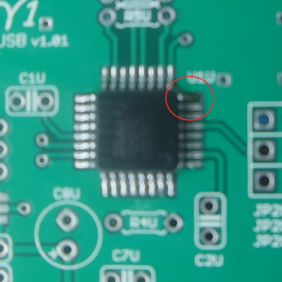
Just a few notes, as a result of me not being able to comprehend simple instructions I have no J4U and have jumpered L3U and R7U.
I haven't jumpered to the DAC board yet, however, testing the USB board hasn't been succesful so I'll worry about that first.
The first 5v is reading fine, the second 5v starts at about 1.2v and declines and the first 3.3v is bumming around down near 0.01v. -.-
mattcalf, R7U (and LEDU) need not be installed at all (no jumpers) for a γ2 build. But these are not likely to be a problem for you.
If by "first" and "second" 5V you refer to the 5V test pads near J2U's VBUS and VCC, then you probably forgot to put a jumper across those two pins. The jumper is needed when you're testing the USB board without the DAC board mated.
Finished the gamma2, everything fits together swell. Is there any 1uf 63v cap I can take off the gamma1 and give to the gamma2 (C26)? Buying an extra one from farnell would set me back AU$25 ($5 each, min. order 5)
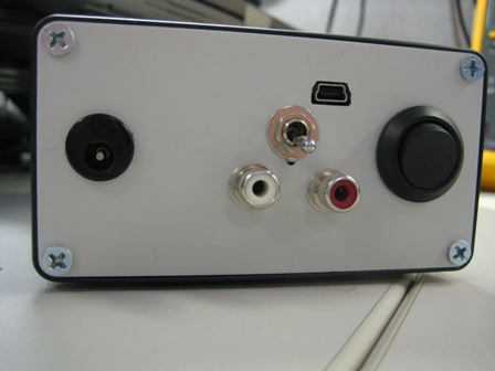
Again a mistake on my part has left me with one less. I don't plan to use anything other then USB in RCA out for the foreseeable future.
Thanks in advance.
EDIT: Is it safe to do the initial testing from AMB's website without C26 there?
mattcalf, C26 is a 22uF audio grade eletrolytic cap, not 1uF.
If you mean C25, and you won't be using the S/PDIF outputs on the front panel, you could steal γ1's C11U. And yes, it's "safe" to test without C25 in that nothing would be damaged, but if C19 is populated then your two channels will be mismatched.
Originally Posted by ramus /img/forum/go_quote.gif Is it dangerous to drive headphones directly out of y1?
Thanks
No, it's not dangerous, see the y1 website, under "parts list". You need to use software volume control since y1 doesn't have one. Also, the output coupling capacitors need to be increased to 470uF if you plan to drive low-Z headphones.
Alright thanks for that, having a problem with the combo no longer being picked up by windows and on second attempt it seems that the input selector switch no longer shows colour. I can see a faint hint of red, however, when I first tested both boards together the red was strong and obvious.
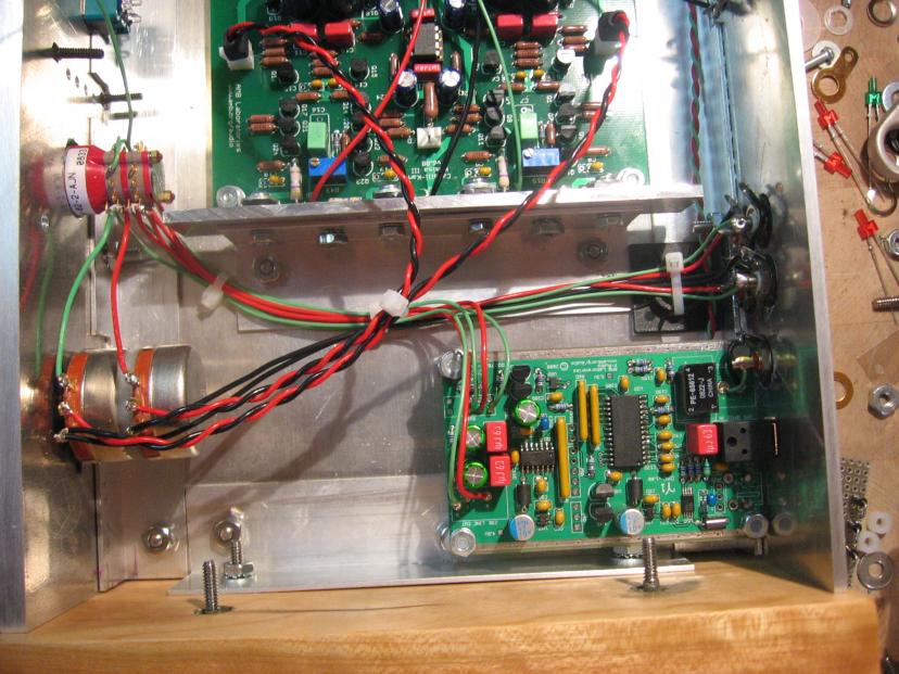
My second problem is gamma2 specific but I'll post it here to save trouble. The 4.5v on the gamma2 only reads about .1v. I have a feeling this should be caused by U1, so I'll check my soldering job on it.
Also my jumper pin on the gamma1 (JP1D) to gamma2 (J3) might be a little bit short , (1mm, 2mm max.) could this be causing any problems?
Also my jumper pin on the gamma1 (JP1D) to gamma2 (J3) might be a little bit short , (1mm, 2mm max.) could this be causing any problems?
Possibly, check the 5 volt test points again and see if the readings would account for the other symptoms you have described.
(the voltage can be pulled low enough that nothing else will work if U1 is short circuited)
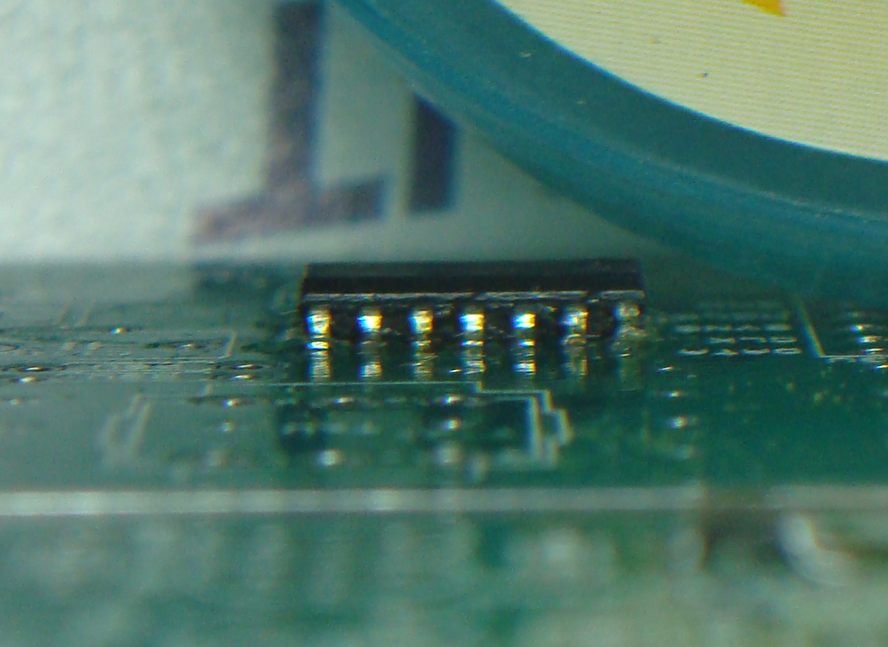
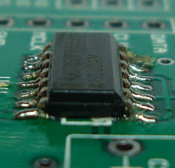
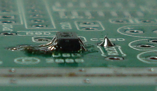
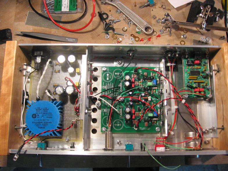
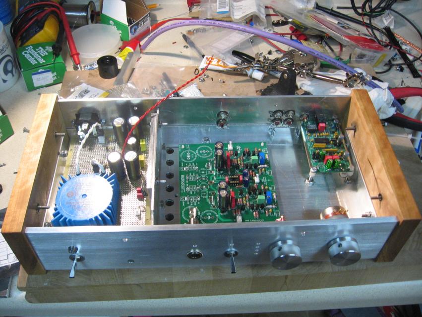
I didn't think they'd turn out too well, luckily my brother's camera takes some half-decent digital ISO pictures.
It looks rather messy and I haven't got around to a DSE, which is the reason for so much flux residue. Man, flux is great.. really didn't think it'd make that much of a difference but that stuff is magic. As is desoldering braid!
Did you use the WM8741 or WM8742 DAC on your gamma 2? If so, U6 should be omitted (see note 1 on the gamma 2 parts list). However, if you used WM8740, you are ok
This site uses cookies to help personalise content, tailor your experience and to keep you logged in if you register.
By continuing to use this site, you are consenting to our use of cookies.


 .
.
 I have no J4U and have jumpered L3U and R7U.


