About line in- and outputs, levels, impedances and cables between.
The past days this thread experienced a lively discussion amongst other things about the line outputs of HPA V281, their quality and if they are about to alter the sound – and if yes to the better or to the worse.
My opinion is that the line outputs from V220 / V281 are altering the sound by at least a very very small fraction (if any) because we worked hard to amend the signals as little as possible.
The key to unaltered sound is to take care about the impedances.
The output impedance of every electronic output shall be kept as low as possible, about 30 ohms or less. The input impedance of the following input shall be reasonably high, about 5 kOhm or more.
By doing so, all involved components – output circuitry, cable, input circuitry - will act as transparent as possible.
Also the overall gain should be as low as possible, the output level should be reasonable and preferably match the following stage and of course the frequency range should be sufficiently wide.
A low output impedance can only be made electronically with some active circuitry, mostly an op-amp or a discrete circuitry similar to an op-amp.
Any resistor in the output line will increase the output impedance and so make the output signal and the cable to the following unit sensitive for frequency alterations, EMC problems and other issues.
Remember: The higher the output impedance the higher the influence of the cable.
Don’t waste money for “sophisticated” cables but invest in low impedance outputs.
As a result from the above a passive attenuator will not work (never !!), because its output is variable and high impedance state.
Yes, some may claim that it sounds better - but its only sounding different !
Also, splitting cables should be avoided (driving two inputs from one output) as the generated impedance mismatches cannot be controlled.
To deal with high levels, the analog circuitry needs an appropriate operating voltage:
For about +21 dBu (approx. 9 Veff) analog level a supply voltage of +/- 15 volt is needed
For about +23 dBu (approx. 11 Veff) analog level a supply voltage of +/- 18 volts is needed
For about +24 dBu (approx. 12 Veff) analog level a supply voltage of +/- 20 V is needed.
Unfortunately many of the “sophisticated” op-amps and transistorized op-amp supplements are only suited for +/- 15 V. Also, the distortions will rise noticeably the closer the signal comes to the limits defined by the operating voltage.
Now you may ask yourself: why there are these high levels from (professional) D/A converters while my (consumer) CD player outputs about +4/+6 dBu.
An answer is the different (professional) conversion standards from digital levels to analog levels.
The US standard (SMPTE RP 155) define the digital full scale level (0 dBFs) to be translated into +24 dB analog level. The European Broadcasters (EBU R68) are translating 0 dBFs to be +18 dBu while the German Broadcasters (IRT) are converting the same digital level to be +15 dBu.
So, some equipment claiming to be made to “professional” standards will output +24 dBu analog level which may perhaps override the inputs of the subsequent (consumer) equipment or is on the edge to considerable distortion.
Some of these units/manufacturers don´t care for “consumer” needs and do nothing.
Some are adding passive attenuators to lower the level – what is the wrong measure because
it scales up the output impedance (see above).
Some are adapting the analog level in an active way, preserving the low output impedance.
Guess what we do at Lake people / Violectric.
Please note that all D/A converter chips are powered from 5 V or less single supply voltage. So the maximum output level of such chips is +8 dBu or lower.
When a D/A converter outputs +24 dBu this means that the signal is boosted by at least +16 dB inside the unit, raising probably hiss and noise - to be unnecessarily attenuated in an appropriate way to fit the following equipment …
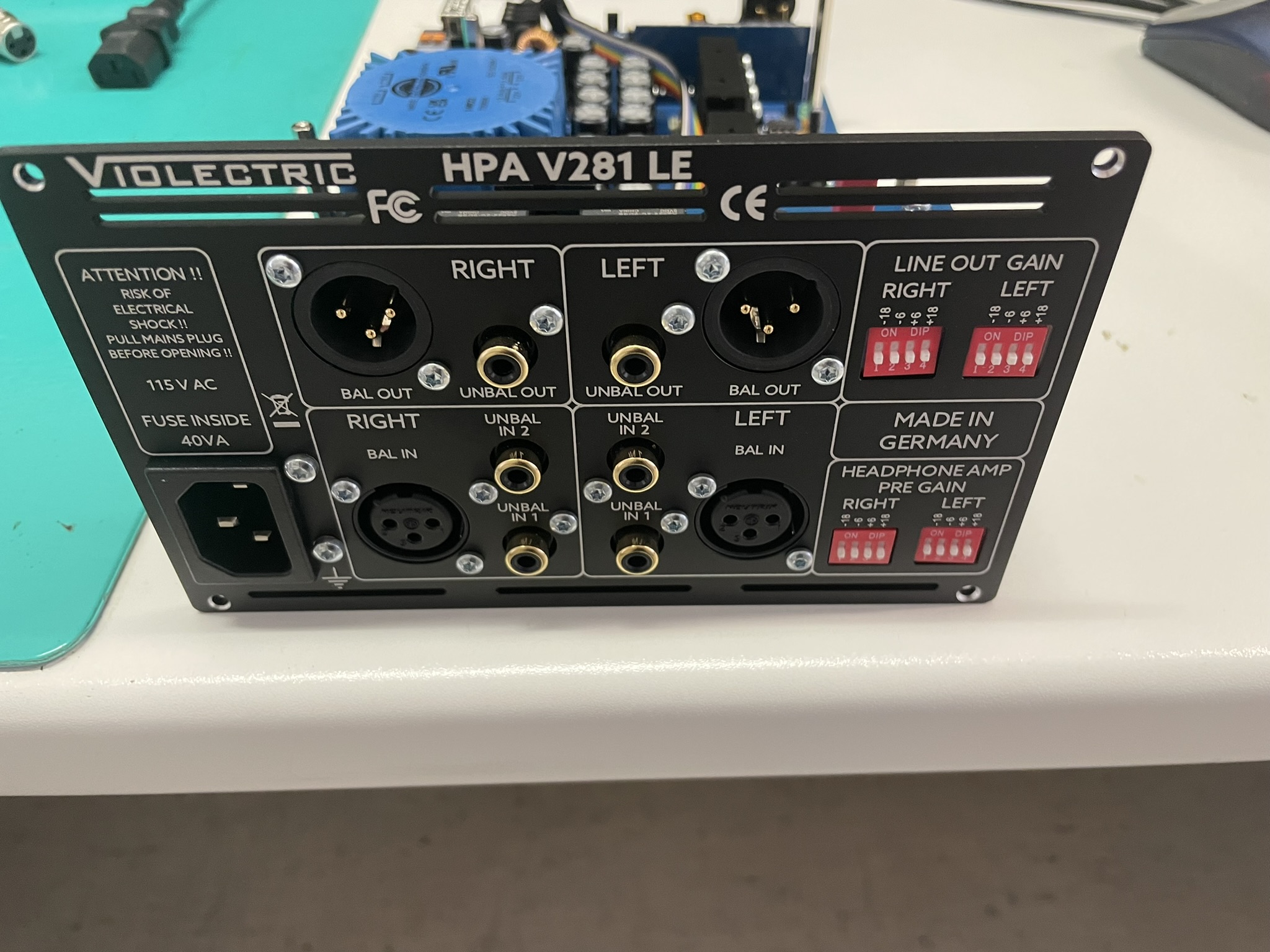
Coming back to HPA V281 and most other lake People and Violectric gear and the treatment of the line output signals I want to make clear that we had the above problems in mind and engineered our input/output circuitry as optimal and variable as possible.
Our line outputs have very low impedances ( < 1 Ohm).
The output levels are adaptable by dip-switches or multi-turn attenuators to match the subsequent gear. This circuitry is found in front of any output circuitry.
Of course it is imaginable that a power-amp and speaker or active speaker will sound different through other devices – but if this is “better” or “worse” are personal preferences.
We do our best not to change anything !


") Lake People product request: +1 for a FPGA DAC card and/or stand alone DAC with DSD/MQA capabilities.
Lake People product request: +1 for a FPGA DAC card and/or stand alone DAC with DSD/MQA capabilities.

