Valab NOS DAC, did I butcher it? EXPERT needed.
May 6, 2011 at 11:24 PM Post #16 of 31
audiocr381ve: Apologies, as I attempted to merge your three threads and the third one was eaten by the system.  I'll try and grab those posts back though.


Quote:
Guys, I apologize in advance for multiple threads, I just wanted to be more direct. My Valab DAC is the version that has a clipping issue. The manufacturers fix is to lower the value of the resistor. I have a few options but I have absolutely no idea how to parallel resistors. Please read the option I have which I outlined in the quote.

Quote:
Don't know if this what you're looking for.


Originally Posted by TeraDak
For those concering the clipping issue.
We current use a 390R resistor for the i/v conversion and it will output 2.19V at the full range audio data. It is impossible to listen the 0-db audio signal from the DAC , to pre/power amplifier and to speaker without any attenuation. It the source doesn't exceed -3db, there will be no clipping issue. However, if you would like to attenuate the signal in the preamplifier and keep the range as full as possible and without clipping. The i/v resistor in the TDA1543 output should be lowered to 340R ~ 350R to avoid clipping. The clipping issue is just a tradeoff for signal attenuation and it depends on the user listening condition. We will show the picture for analog output with i/v resistor 340R ~ 350R. For signal analysis, it should be 340R~ 350R, but it may not be the best for users in most real listening conditions.

(1) For user using the original 390R resistor, if you care about the clipping issue, you can reduce the resistor to 340R ~ 350R without loss the audio quality. If you don't have 340R ~ 350R resistor at hand ( 340R ~ 350R resistor is difficult to buy), you can parallel a 3.3k or 3.6k on the original 390R resistor. However, a 330R resistor is good aslo. The main difference is the maximum output voltage when a 0db signal is input.

(2) After that, connect the USB line to our DAC and repeat playing a 1kHz 0DB sine wave in PC. The wave could also be downloaded form our share space ( Public - Windows Live )
Use a meter and set it to measure AC voltage segment. Measure the RCA output or our DAC. The AC output is approximate 2.0V initially. Trim the VR nearby TDA1543 to find the maximum AC output. We usually trim the VR with the help of scope. But a meter is also good enough for tuning. If you have a scope, you can trim the VR such that the sine-wave is the most symmetric. The most symmetric output implies the maximum AC output in a meter.

The second step can be skipped it there is no meter or scope at hand. There is only few difference after step (2) adjustment.
/********************** Notice **********************/
The most important should be noticed is the VR trimming should be after the DAC power-on 30 mins. After that, the DAC will be in a stable state for adjustment. In the first 30 min, the TDA1543 was not in a stable stage. Trimming in the unstable state is no use.
/**********************************************/


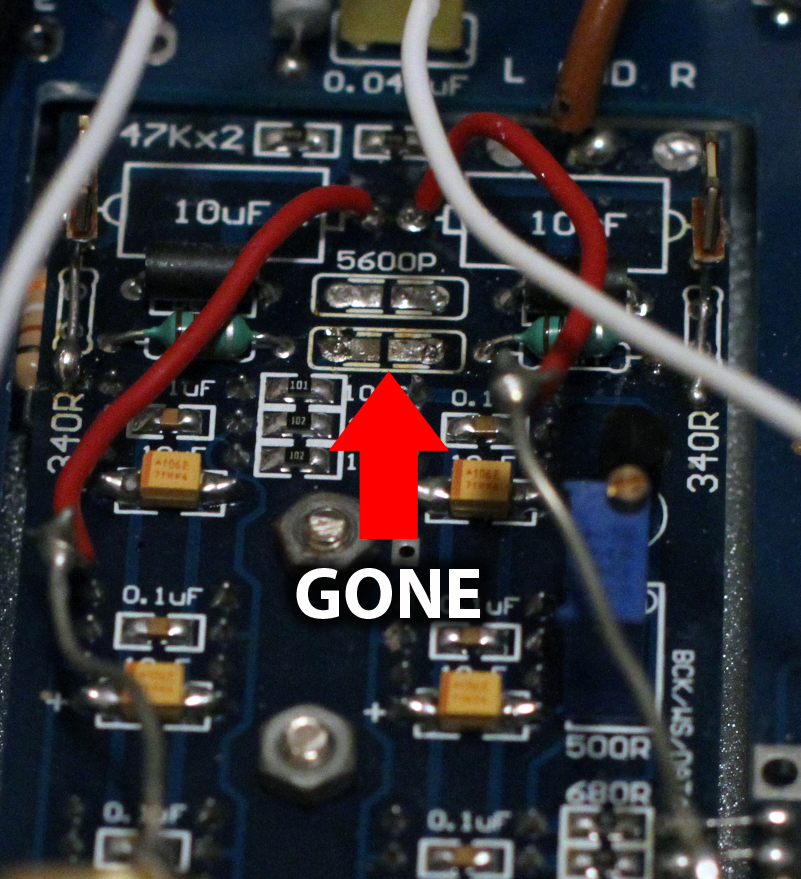
I do not want to remove both 390R resistors because the traces are on their last breath. Outlined above is an option to "Parallel" a 3.3k resistor (is 3.3k also known as 330k? Because I have a few of those) 


If someone had some type of illustration or could explain it very slowly, it would help a lot. 


May 10, 2011 at 12:35 PM Post #21 of 31
Caps need to be installed a certain way about. Like diodes. Otherwise bad things happen. The board is usually marked with a symbol ( a plus or minus symbol typically) and the caps are also marked (generally with just minus, although sometimes plus) to indicate that. The legs on the caps are also different lengths, with the shorter lead being the "minus" lead.
 
wikipedia capacitor
 
May 10, 2011 at 12:43 PM Post #23 of 31


Quote:
Whoa, I'm afraid I don't even know what that means!
 
Would a kind soul please explain what's going on here? Caps polarized or not polarize? Output caps backwards? Whaaat?


Electrolytic capacitors have a polarity [ + and - ]. These types only function in one specific way, if they are hooked up in reverse, they will be reverse-biased and most likely be destroyed.
 
Below are through hole and surface mount types of polarized capacitors. The stripe and arrows usually represent the (-) terminal of the capacitor, but this is manufacturer dependent. Typically, the circuit board will specify where the (+) terminal goes.


Quote:
Are their some caps that don't need to be installed like that? These are the Obbligato Gold Premium caps. 
 
Would be a huge bummer if I had them in wrong the entire time.


If the caps do not have a stripe down the side and the circuit board does not specify a (+) terminal, then you will need non-polarized caps. Film caps are non-polar, does the circuit board require a polarized one? Did the caps you remove have a stripe on the side?
 
May 10, 2011 at 12:49 PM Post #24 of 31
Obbligato Gold Premium caps are polypropylene film in a non-magnetic case.
Are you sure they are polarized? I don't think they are, but I have been known to
be wrong...
 
May 10, 2011 at 2:02 PM Post #25 of 31
Thank you for explaining that to me. You'd be the first! 
 
I know for sure that the board doesn't specify (it WAS made in China though, I'm assuming they could forget something like that?)
 
May 10, 2011 at 2:32 PM Post #26 of 31
In the absence of any markings, it is usual that the negative side
of the cap goes to the output connector and the positive side
of the caps goes toward the circuitry.
 
May 10, 2011 at 3:40 PM Post #27 of 31
Wow, this whole time.............
 
Well, what happens if it sounds good right now? I've compared this DAC to the analog outs on my CD player and the DAC is sounding nicer and more bodied. Hmmm...
 
Any thoughts?
 
May 10, 2011 at 6:36 PM Post #28 of 31


Quote:
Wow, this whole time.............
 
Well, what happens if it sounds good right now? I've compared this DAC to the analog outs on my CD player and the DAC is sounding nicer and more bodied. Hmmm...
 
Any thoughts?

Well, since I was just basing my explaination off of the suggestion of someone else saying that the caps look like they are backwards, I'm not certain that it was your problem. If the device works, then the caps aren't hooked up improperly.


May 10, 2011 at 6:43 PM Post #29 of 31
film caps are usually "non-polar", but that only means they don't have to be wired a certain way (i.e. you can connect either way without causing damage). There is still a sound difference if  you wire them in reverse: the mids get emphasised a bit and sound stage become narrower, typically. Not bad if you only care about voice replay.
 
Try reversing the wires and see if you like the sound better.
 
May 10, 2011 at 10:35 PM Post #30 of 31


Quote:
film caps are usually "non-polar", but that only means they don't have to be wired a certain way (i.e. you can connect either way without causing damage). There is still a sound difference if  you wire them in reverse: the mids get emphasised a bit and sound stage become narrower, typically. Not bad if you only care about voice replay.
 
Try reversing the wires and see if you like the sound better.


I would be interested in articles explaining this phenomenon as I cannot wrap my head around it.


Users who are viewing this thread

Back
Top